0
\$\begingroup\$

I have an interesting behaviour with my electronics project. I am trying to do something like a LED array but with electromagnets instead. See the schematic below. I built the magnets myself by winding 5 meters of 0.3mm magnet wire around iron nails. I use relays for the switches. The diodes are rated for high currents.

When I pulse one of the top switches and one of the bottom switches together, I expect only one coil to get powered. BUT the interesting thing is that EVERY magnet pulses a magnetic field, just the one that SHOULD pulse has a more powerful field. I can feel that by holding a permanent magnet next to it.

Please can someone explain this to me, because I dont see how the current can enter the non-connected coils.
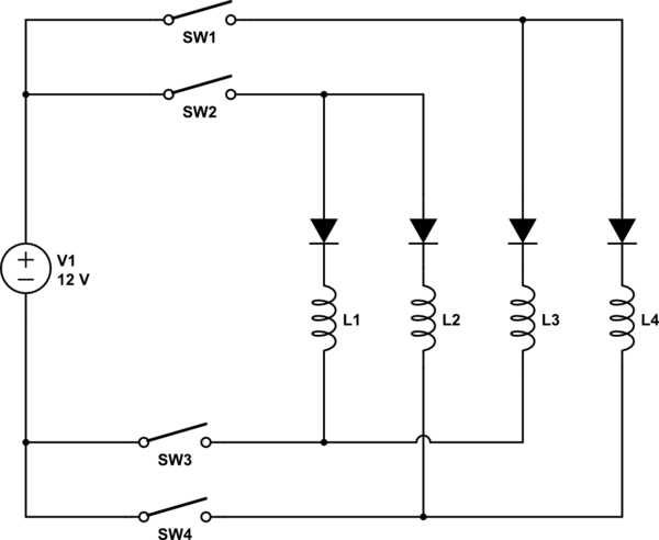
schematic

simulate this circuit – Schematic created using CircuitLab

\$\endgroup\$
7
  • \$\begingroup\$ Are you magnetically isolating the relays from the nail-coils? \$\endgroup\$
    – Andy aka
    Commented Nov 28, 2018 at 16:41
  • \$\begingroup\$ what purpose do the diodes serve? you should definitely put flyback diodes (anti-parallel with the electromagnets). \$\endgroup\$
    – thece
    Commented Nov 28, 2018 at 16:43
  • \$\begingroup\$ the relays are at the other side of my table. the diodes are important because if i close one switch at the top and one at the bottom there must be only one path for the current to flow! \$\endgroup\$
    – Fri Klein
    Commented Nov 28, 2018 at 17:44
  • \$\begingroup\$ @FriKlein I don't see how removing the diodes would change that? \$\endgroup\$
    – Hearth
    Commented Nov 28, 2018 at 17:57
  • 1
    \$\begingroup\$ @thece: The diodes prevent sneak paths. They are required in matrix switching. \$\endgroup\$
    – Transistor
    Commented Nov 28, 2018 at 18:08

1 Answer 1

1
\$\begingroup\$

Of course, permanent magnets are attracted to the iron with no current flowing. Iron is ferromagnetic.

If you don't have a more-or-less closed magnetic circuit, a lot of the field lines will go through the air and, if the cores (nails, in your case) are close then there will some effect on the nearby core when your coil is energized.

You should have diodes across the coils (in parallel), reverse biased, of course, to prevent the (high voltage) turn-off spike from possibly killing the series diodes.

\$\endgroup\$
4
  • \$\begingroup\$ do you suggest putting the flyback diodes parralel to the coil AND the existing diodes? the problem is that doing this the whole matrix will stop working. It is important that there is always only one way through one coil when two switches are closed. \$\endgroup\$
    – Fri Klein
    Commented Nov 28, 2018 at 17:42
  • \$\begingroup\$ The flyback diodes will have no effect when on the normal operation. The parallel diode will only conduct briefly when the relevant coil is de-energized. There is still only one way through the matrix because of the series diodes. In fact, you could "scan" such an X-Y matrix and maintain continuous current in any number of desired coils if the scan time was small in proportion to the L/R time constant. \$\endgroup\$ Commented Nov 28, 2018 at 18:02
  • \$\begingroup\$ so do you think I already killed my diodes and because of that the matrix is not working as expected? \$\endgroup\$
    – Fri Klein
    Commented Nov 28, 2018 at 18:04
  • \$\begingroup\$ If your diodes are typical 1N4005 type diodes I think it unlikely. \$\endgroup\$ Commented Nov 28, 2018 at 23:22

Your Answer

By clicking “Post Your Answer”, you agree to our terms of service and acknowledge you have read our privacy policy.

Not the answer you're looking for? Browse other questions tagged or ask your own question.