1
\$\begingroup\$

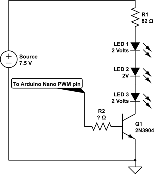
I am new to electronics and creating my first big project but I am stumped on figuring out the value of the base resistor (R2 in diagram) of an NPN 2n3904 transistor. All of the LED are rated for 20mA. I have done a lot of research but the more look in to it, the more I am confused. Any help on this issue would be greatly appreciated!

schematic

simulate this circuit – Schematic created using CircuitLab

\$\endgroup\$
4
  • \$\begingroup\$ R2 is calculated to produce a Vce(sat) rating when Ic/Ib=10 close to 10% of the hFE rating in the linear range. thus 2mA can be computed by (Vout-0.7)/2mA=R2 But you can tradeoff off some Vce (sat) rise for drop in V(R1) thus use a smaller R1 like 50 to 62 Ohms. A quick estimate is R2=10x R1 for the desired Ic current, But that 10 is often relaxed to 20x. with neglible difference in Vce(sat) \$\endgroup\$
    – D.A.S.
    Commented Dec 2, 2018 at 1:23
  • \$\begingroup\$ The purpose of the resistor is to protect the nano pin. Without a resistor the transistor looks just like a diode (the BE junction), and will dump all the current put into it. This will damage the nano pin and the transistor. Nano pin likely has a 20mA limit. Required collector current divided by hFE (see datasheet curves) will give the required base current. Set the resistor accordingly. If the required base current is too high, you will need a darlington configuration. \$\endgroup\$
    – Indraneel
    Commented Dec 2, 2018 at 1:28
  • \$\begingroup\$ The Nano has a 25 to 50 driver impedance so it can easily drive 10xR1 to base but using hFE has a lousy tolerance so the tendancy is to saturate the transistor for better accuracy with over-drive on base current as MOT called it in the late 60's \$\endgroup\$
    – D.A.S.
    Commented Dec 2, 2018 at 1:31
  • \$\begingroup\$ example: you need 10mA for the led chain. hFE at 10mA collector current is 150 (onsemi datasheet onsemi.com/pub/Collateral/2N3903-D.PDF figure 11). Minimum base current is 10mA/150=66uA, i.e. (5-0.7V)/66uA=65K. However, transistor may heat up a bit as collector emitter voltage is a bit high here (see figure 16). Increasing base current 10 times to 1mA, reduces 1V drop to 0.1V drop (10 times). Resistor becomes 4.3K. So anyting from 1K to 10K would be fine. I would use 10K just because it is more common and reduces excess current. \$\endgroup\$
    – Indraneel
    Commented Dec 2, 2018 at 1:41

3 Answers 3

3
\$\begingroup\$

You have a bit under 20mA going to the LEDs (the Vf's are not all that well controlled, so let's use 20mA).

For the 2N3904 the Vce(sat) is guaranteed at 10mA and 50mA (bracketing your 20mA collector current) at Ic/Ib = 10. We can relax that to 20 without any serious problems since hFE is between 60 and 100 minimum (measured with Vce = 1.0V). All this stuff you can find in the datasheet.

So you want 1-2mA base current.

Since the Arduino nano has a 5V supply, the output will be close to 5V if you don't load it too heavily (you'll have to check the ATMega328p datasheet for the characteristics).

We know the base voltage is about 0.7V when 'on', so the voltage across your base resistor will be 4.3V or so. So the resistor should be somewhere around 4.7K to 2K roughly.

\$\endgroup\$
0
\$\begingroup\$

Many replies here talked about hFE which is not used for this transistor used as an on-off saturated switch. hFE is used for a linear amplifier that has plenty of collector voltage, not for a saturated switch that has a very low collector voltage. The datasheets show the base current is guaranteed to saturate the little transistors when the base current is 1/10th the collector current.

Where can you buy an LED with a 2V forward voltage? Nowhere, they have a range of voltage which might be 1.6V to 2.2V for a red LED. If yours are all 1.6V then the current with the 82 ohms resistor will be 30.5mA which might burnout the LEDs.

EDIT again. The graphs on a datasheet are for a "typical" transistor that you cannot buy. Your transistor might have a gain much less than typical then not work so if you use the minimum spec's in your calculation then your circuit will work with a transistor that is passing but is less than typical.

\$\endgroup\$
1
  • \$\begingroup\$ Yes do you recall MOT's definition in the earliest data sheets for transistors defined it as a beta overdrive factor vs Vce reduction < 1V or reduction in effective hFE down to 10% of max according to datasheets for those with max hFE in modern Diodes Inc parts with hFE 500 to >2k and Ic:Ib ratios of 50 minimum are then only needed to achieve Vce(sat) specs now 1.6V RED LEDs were the old GaAs types not the AlinGaAs used now. (Aluminum Indium Gallium Arsenide) \$\endgroup\$
    – D.A.S.
    Commented Dec 2, 2018 at 2:19
0
\$\begingroup\$

Figure 16 of https://www.onsemi.com/pub/Collateral/2N3903-D.PDF indicates if you interpolate between 10 and 30mA to get 20mA , you can choose a saturation voltage of either 0.20 or 0.30V for Vce to get approximately 230 uA or 400uA of base current respectively.

Computed as a ratio of collector current and accounting for Vbe drop of 0.65 to 0.7 one gets an effective current gain of 20m/230u = 87 @ 0.3Vce to 20m/400uA = 50 @ 0.2Vce

The table specs use a defacto ratio of 10:1 Ic:Ib for Vce(sat) results for the lowest practical worst case (max) saturation voltage, but the chart shows a lower nominal Vce

So hFE=50 a maximum effective value @ Vce=0.2 V Rb=(5V-0.7{Vbe})/400uA= 10.8k Ohms

more
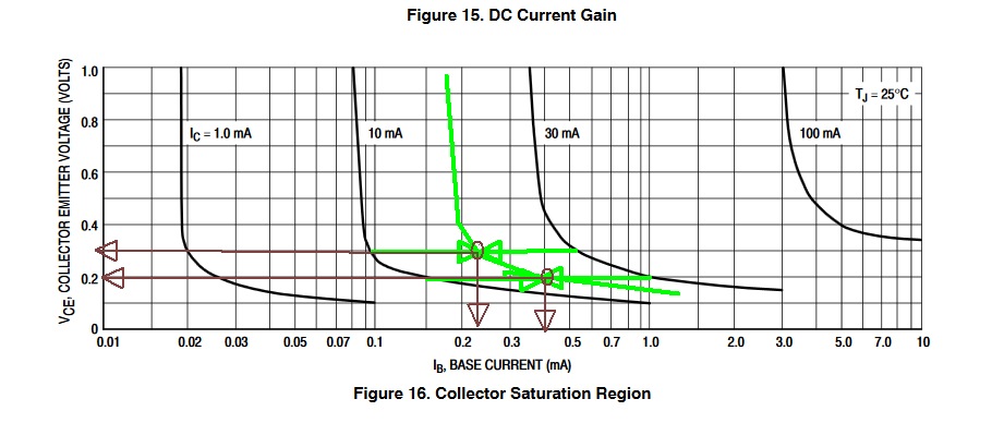
enter image description here This proves ( as suggested in comments) that anything between 1k and 10k works with slight reduction in collector current from a rise in Vce. You can achieve a nominal linear hFE of 150 ONLY if Vce>=1V @ 10mA and perhaps 160 if Vce is higher. Yet hFE has a very high tolerance, so we use conservative values to get better results as a "switch".

Linear Hfe current gain is spec'd here for 100 to 300 @ 10mA @ Vce=1.0V in the tables for the 2N3904. These apply to generic supplier specs too.
\$\endgroup\$
1
  • \$\begingroup\$ capitalize the 1K and 10K !!! (like I did) ;) nice explanation! This explains the voltage drop across series pass transistors in power supplies. \$\endgroup\$
    – Indraneel
    Commented Dec 2, 2018 at 18:50

Your Answer

By clicking “Post Your Answer”, you agree to our terms of service and acknowledge you have read our privacy policy.

Not the answer you're looking for? Browse other questions tagged or ask your own question.