0
\$\begingroup\$

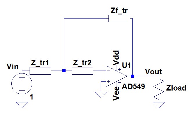
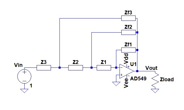
I have been trying to figure out how the following circuit works and what it might be good for without any luck so far.

What might the transfer function be?

Is there a way that analysis can be applied generally to many such loops inside each other ?

(for analysis purpose exact op amp type does not matter, and may be considered ideal)

op amp multi feedback

Upon recommendation, i tried the delta-star transformation, and came up with conclusion that n loops can be simplified to the circuit below:

op amp feedback transformed

This looks like inverting op amp but there is one resistor left from the last transformation connected to inverting input. Is this correct, or am I missing something ?

\$\endgroup\$
1
  • \$\begingroup\$ In principle, the calculation follows the same rules as we are using for the active lowpass in MFB topology (Multi-Loop-Feedback). It is somewhat involved, but not a fundamental problem. \$\endgroup\$
    – LvW
    Commented Dec 5, 2018 at 20:25

4 Answers 4

1
\$\begingroup\$

You can always address these types of problems by decomposing them in sub-systems. That's why 2-port network techniques were invented.

You just have to calculate the input/output impedances and the transfer function of the successive inner stages, and use the simplified models to solve the enclosing stages.

But be sure to consider the exact type of amplifier you have, to avoid making mistakes. Although in this case it does not really make a difference, an inverting op-amp configuration is in general a trans-conductance gain stage with a voltage to current conversion at its input.

In this case, the innermost stage is simply an ideal voltage-dependent voltage source with transfer function Vout = -Zf1/Z1 * V1, input impedance Z1, and output impedance 0.

From then on you have to use actual feedback equations (the only ideal element remaining is the zero output impedance) to calculate the rest of the feedbacks.

\$\endgroup\$
1
\$\begingroup\$

This is relatively easy to reduce to a basic opamp configuration (not spoiling which one that is) by applying the standard basic transformation on linear networks that you know!

So, for example, you could start by doing a bunch of Y-Δ transforms:

  • Z2, ZF2 and ZF3 form a Δ. Transform to Y.
  • Z3 + the left leg of that Y can be combined.
  • Z1 + the right leg of that Y can be combined.
  • You'll find another Δ, this time including ZF1. Rinse and repeat.

So, this is really just an exercise in the techniques you already know!

\$\endgroup\$
1
\$\begingroup\$

Perhaps not yet the most popular way of analyzing circuits, but you can also exploit the Extra-Element Theorem (EET). It allows you to split up calculations in more simple ones and it can show you how specific elements influence a transfer function.

This circuit would become very simple indeed if we could assume that \$Z_{f2} = Z_{f3} = +\infty\$ (open circuits). The topology would become that of a regular inverting amplifier. The N-Extra Element Theorem tells us that

$$A = A^{(Z_{1}=\infty, Z_{2}=\infty)}\frac{1 + \frac{Z_{n1}}{Z_1} + \frac{Z_{n2}}{Z_2} + \frac{Z_{n1}}{Z_1}\frac{Z_{n2}^{(1)}}{Z_2}}{1 + \frac{Z_{d1}}{Z_1} + \frac{Z_{d2}}{Z_2} + \frac{Z_{d1}}{Z_1}\frac{Z_{d2}^{(1)}}{Z_2}}$$

Although it looks rather complex, each of those terms is actually relatively easy to find once you understand how - which admittedly does take some time and convincing first. Using \$Z_1=Z_{f2}\$ and \$Z_2 = Z_{f3}\$:

$$\begin{align} Z_{n1} &= 0\\ Z_{n2} &= 0\\ Z_{d1} &= \left(Z_1 || (Z_2 + Z_3)\right)\cdot\left(1 + \frac{Z_{f1}}{Z_1}\right)\\ Z_{d2} &= \left(Z_3 || (Z_2 + Z_1)\right)\cdot\left(1 + \frac{Z_{f1}}{Z_1 + Z_2}\right)\\ Z_{d2}^{(1)} &= Z_2 || Z_3 \end{align}$$

Don't take my word for these calculations though, I just did these ones by inspection just before going to bed without double checking.

\$\endgroup\$
1
\$\begingroup\$

The systematic (more formal) way would be to use Kirchhoffs laws for the three nodes of the passive network. Allocate node voltages (against ground) to each node.

  • Node 1 between Z3 and z2

  • Node 2 betwee Z2 and Z1

  • Node 3 identical with the inverting input (voltage Vn=0)

Write down the equations for each node : (current in=current out).

As a result, you will get three equations for the three unknowns: Vn1,Vn2, Vout/Vin. This system of three equations can be solved.

\$\endgroup\$

Your Answer

By clicking “Post Your Answer”, you agree to our terms of service and acknowledge you have read our privacy policy.

Not the answer you're looking for? Browse other questions tagged or ask your own question.