0
\$\begingroup\$

I have a PIR: Panasonic NaPiOn AMN34112 that has a digital output. When it detects motion it outputs 4V and 100 uA max. I want to connect this output to a LED using one or more transistor amplifier stages. Before I do that I want to model what happens in the circuit simulator Every Circuit. How do I model a digital output? I want to make sure I am not sourcing more than 100 uA from the PIR. I was thinking modelling the PIR as a 4V battery. Is this wrong?

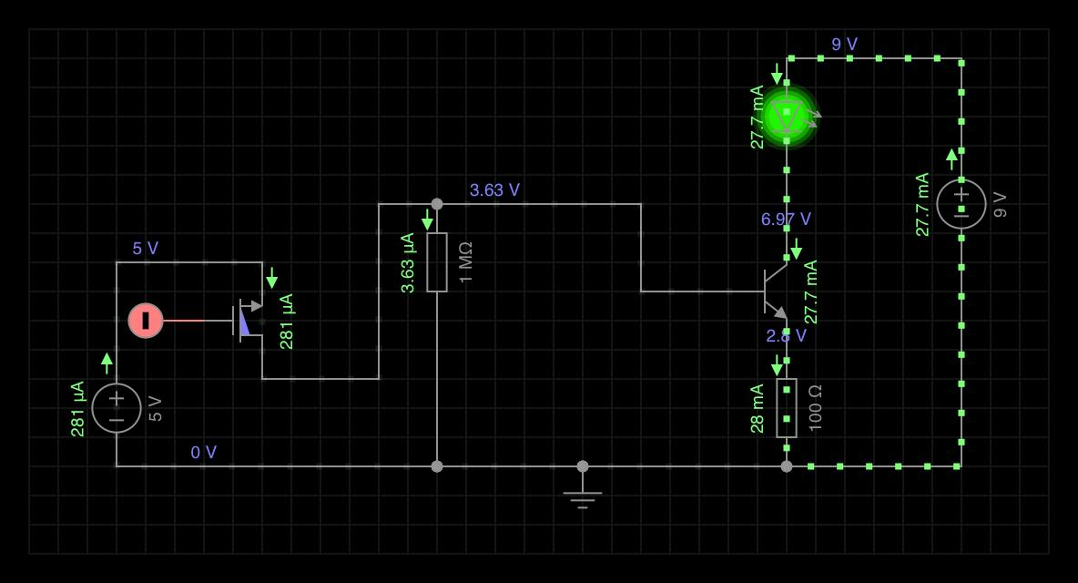
EDIT: after reading your answers I understand that this is very wrong. Instead I will try this:

enter image description here

I used the default mosfet in the circuit simulator. In this circuit it has a voltage drop of V_SD = 1.4 V whereas I_DS is 281 uA => R_DS(on) = 1.4/2.8 E-4 = 5K Ohm which is the same as you mentioned.

\$\endgroup\$
1
  • 1
    \$\begingroup\$ model it as a 100uA current source. Since it is going into an amp stage, it being digital doesn't matter. I think you can do it with one amp stage. You need about 2mA for an led and that is a 20 to 1 current amplification. Getting a transistor with a beta of 20 or more is easy-peazy. \$\endgroup\$
    – zeta-band
    Commented Dec 7, 2018 at 16:48

2 Answers 2

2
\$\begingroup\$

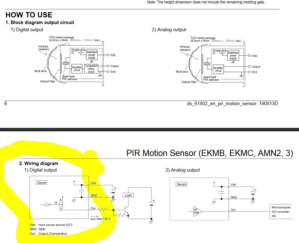
Use the schematic in the datasheet as your model.

When active 0.5V drop from Vdd at 100uA the Pch-FET from datasheet

Output ≧ Vdd-0.5V so 4.5V Min from Vdd=5V. If you draw 200 uA then your output drops to 4V at the most, which is why you may have misstated the problem.

  • FET has series resistance or RdsOn <= 0.5V/0.1mA = 5kΩ = Output pullup equivalent circuit

When inactive Out = open circuit = off enter image description here

\$\endgroup\$
4
  • \$\begingroup\$ Thanks for your help! Assuming Vdd = 5 V does this mean that If I connect the Out of the PIR directly to ground it will source 1 mA without being destroyed? \$\endgroup\$
    – Andy
    Commented Dec 7, 2018 at 19:29
  • \$\begingroup\$ yes its ok. the current is limited by V/R but you should use the cct to activate the transistor and invert the voltage. and choose R ratio for the threshold at 0.65V = Vbe \$\endgroup\$
    – D.A.S.
    Commented Dec 7, 2018 at 19:38
  • \$\begingroup\$ Thank you for your help. I have added a circuit diagram to my question and will try that out on the bredboard. \$\endgroup\$
    – Andy
    Commented Dec 7, 2018 at 20:04
  • \$\begingroup\$ Avoid the crossing lines and U got your FET DS reversed. \$\endgroup\$
    – D.A.S.
    Commented Dec 7, 2018 at 20:42
2
\$\begingroup\$

No, your sensor does not output 4V and 100 uA. It either provides an output of 4V and the current is determined by what is connected to the output, or it provides an output of 100uA and the voltage is determined by what is connected to the output.

In SPICE you would typically use a pulsed voltage source to simulate the detector output. After running the simulation you would verify that the output current never exceeds the maximum value (100uA in this case).

You really should provide a link to the datasheet of the sensor you are using.

\$\endgroup\$
4
  • \$\begingroup\$ More accurately, it either provides 4V and the current is determined by what is connected to the output, or, if the thing connected to the output draws more than 100\$\mu\mathrm{A}\$ at 4V, the results are not guaranteed. \$\endgroup\$
    – TimWescott
    Commented Dec 7, 2018 at 16:54
  • \$\begingroup\$ Thanks. I have edited my question. I was guessing digital out implied voltage source? \$\endgroup\$
    – Andy
    Commented Dec 7, 2018 at 16:57
  • \$\begingroup\$ Almost Elliot but not quite. \$\endgroup\$
    – D.A.S.
    Commented Dec 7, 2018 at 17:57
  • 2
    \$\begingroup\$ @TonyEErocketscientist As usual, your comment is clear, concise, and informative. \$\endgroup\$ Commented Dec 7, 2018 at 18:17

Your Answer

By clicking “Post Your Answer”, you agree to our terms of service and acknowledge you have read our privacy policy.

Not the answer you're looking for? Browse other questions tagged or ask your own question.