5
\$\begingroup\$

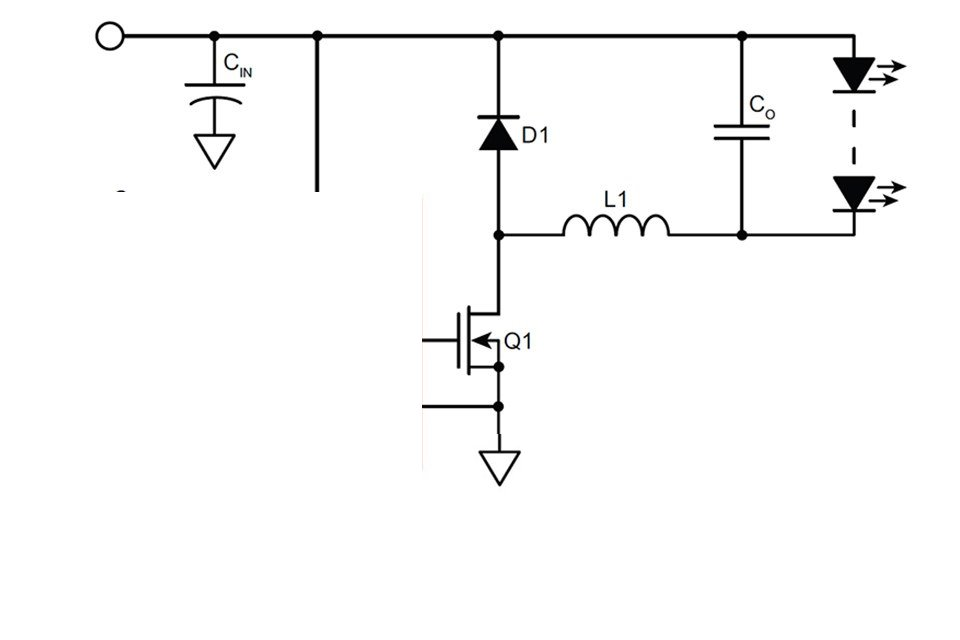
About this buck LED driver...

enter image description here

TL/DR the questions:

1) I intend to drive the FET from a microcontroller PWM via a suitable FET driver. This open loop control scheme seems too simple. Is it a trap? I don't need accurate current control as this is for lighting my living room, 20% error on the current is okay, but I do need a wide dimming dynamic range.

2) Would a high side FET instead of low-side help with EMI by referencing the load to ground? Or will solid decoupling on VCC combined with the output cap be enough?

3) Do I need to put a filter on the output so my wires and strips won't radiate, or will it be okay with the inductor and output cap? The filter will only cost me a ferrite bead since there'll be several paralleled ceramic caps on the output, might as well split them in two groups and stick a ferrite bead in between.

Rest of relevant information:

Power Supply: 24V 10A, adjustable to 25.6V

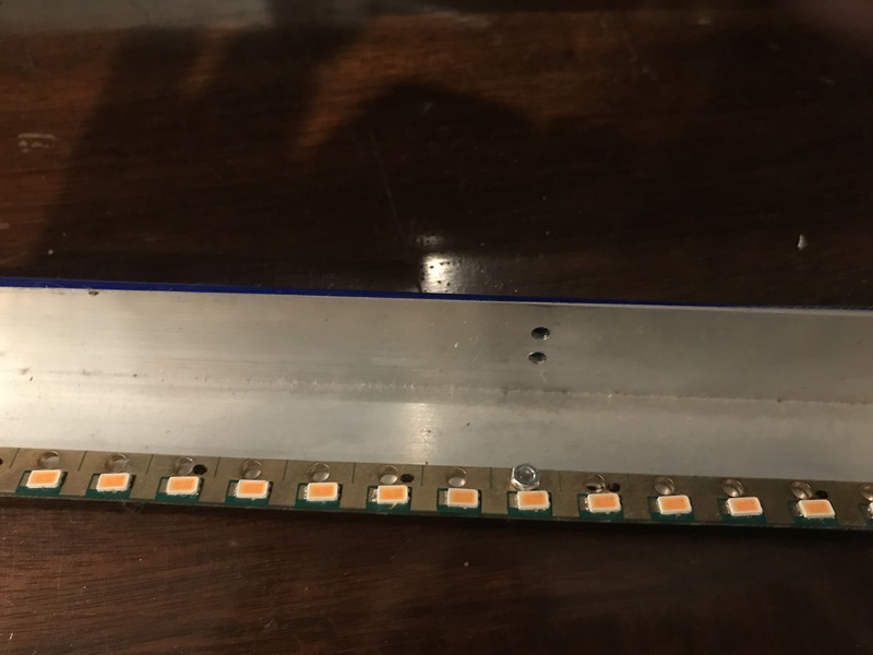
Load: this is for a variable color temperature light which is implemented with 2700K and 5600K LED MCPCB modules. These LEDs have exceptional color rendition. In order to expand the color temperature range, I added 2200K 24V Strips and some 24V Red Strip too for extra coziness. This is mounted on aluminium extrusion. All MCPCBs and strips are designed to be driven with 24V and include resistors.

Each LED color will get one copy of the driver above. Max currents are 5600K LEDs @ 3.6A, 2700K @ 3.6A, 2200K @ 1.5A, Red @ 1A.

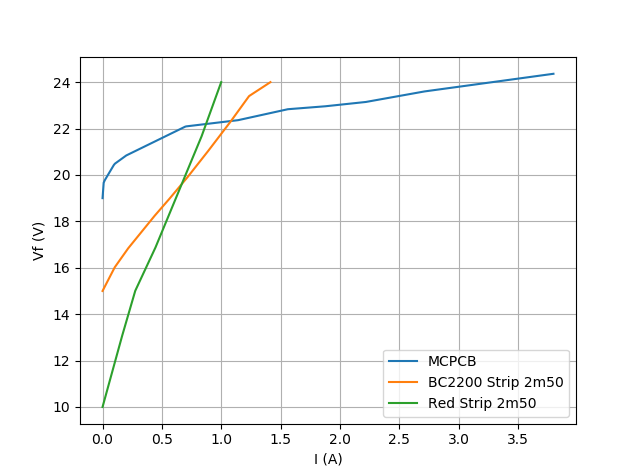
LED IV characteristics, if needed:

enter image description here

Links to datasheets FET Inductor (10µH for high current channels, 22-33µH for the others).

Control scheme:

Frequency will be between 100 and 250k, not decided yet.

Duty cycle is constrained by minimum ON-time and minimum OFF-time, so I'd simply switch to pulse density modulation in software at very low and very high power, ie some cycles would be fully ON or fully OFF, and others would have a pulse. I'd use software dithering (aka sigma delta) to randomly distribute the pulses to make sure it doesn't flicker. This is my preferred option, also it would allow to phase shift the channels, a bit like in a multiphase buck, to reduce demands on the power supply.

When the buck works in discontinuous mode (inductor current reaches 0 and stays there during part of the cycle) each cycle results in inductor current ramping up then down which pumps a certain amount of charge into the output cap, which results in a current source controlled by frequency and ON-time. This is a nice feature. It'll be inaccurate but a 10-20% variation in output is unnoticeable anyway, and it won't flicker. Plus, at very low current, dynamic resistance of the LEDs increases which makes the output cap's RC filtering action more effective.

At high power when the inductor current is continuous, then PWM will simply control the output voltage. In this mode, the resistors on the LED modules dominate their impedance, so they can be voltage-controlled I guess. I measured the voltage on the MCPCB resistors, and it turns out that the current in each series string of LED is very well balanced. The manufacturer bins their LEDs by forward voltage, so that explains it, the LEDs are actually matched. Neat.

I know I'll have to devise a control law from desired intensity to PWM/PDM values, and that it won't be super accurate, but as long as it's monotonous and I can set the intensity and color temperature with +/- buttons on my remote control, that will do just fine.

\$\endgroup\$
4
  • \$\begingroup\$ Maybe bullet point your specific questions somewhere in the answer? It's a lot to read. \$\endgroup\$
    – MadHatter
    Commented Dec 26, 2018 at 18:18
  • \$\begingroup\$ @MadHatter I've added some formatting. Better? \$\endgroup\$
    – bobflux
    Commented Dec 26, 2018 at 18:24
  • \$\begingroup\$ So your questions appear to be “is open loop as simple as it seems” and “will the output LC Filter need a ferrite bead”. If I’m right then scrap 95% of your unnecessary words and focus on the words that are needed only to answer you. \$\endgroup\$
    – Andy aka
    Commented Dec 26, 2018 at 19:48
  • \$\begingroup\$ @Andyaka Yeah you're right, I axed it \$\endgroup\$
    – bobflux
    Commented Dec 26, 2018 at 20:08

2 Answers 2

4
\$\begingroup\$

There is nothing wrong with running this setup as open-loop. Closed-loop is only really needed if trying to achieve some exact repeatable output, like a voltage regulator. In this case, all you're trying to get is a lighted output and the chances of noticing if the voltage is 19.2V or 19.7 after turning the light on are very small.

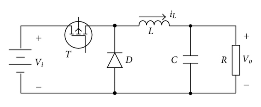
Now what I would suggest is to move the MOSFET to the input of the circuit rather than the output. The circuit as it sits will radiate a lot because the switching current is in the entire thing. By moving the MOSFET to the input the switching currents will be filtered before being delivered to the LEDs. Then by placing the buck converter in a metal enclosure, the radiation will be limited. Be sure to provision for a snubber on the MOSFET. Not having a snubber is a quick way to overheat the FET.

enter image description here

Also, make sure that the inductor is capable of delivering the continuous current if the MOSFET is on all the time without overheating and obviously fuse everything.

\$\endgroup\$
4
  • \$\begingroup\$ "make sure that the inductor is capable of delivering the continuous current if the MOSFET is on all the time" : sure, being on all the time is the max power setting which will be used, so I selected an inductor which allows this. \$\endgroup\$
    – bobflux
    Commented Dec 26, 2018 at 21:19
  • \$\begingroup\$ "move the MOSFET to the input" : ok, this needs a high side driver, will look into these. Are you sure it's worth it vs solid decoupling to tie VCC to GND? \$\endgroup\$
    – bobflux
    Commented Dec 26, 2018 at 21:22
  • \$\begingroup\$ @peufeu Yes, it's worth it. I assume that the wires involved here are longer than a few inches. With the low side MOSFET the entire assembly will become a giant radiating antenna. With the high side MOSFET will keep the switching noise behind the LC filter. \$\endgroup\$
    – vini_i
    Commented Dec 27, 2018 at 12:48
  • \$\begingroup\$ Yeah, wires plus 2m of LED strips which would make nice antenna. I'll use high side drive, ground the strips and link PCB ground to the aluminium extrusion which carries the LEDs and the pcb, so it'll act as a ground plane. \$\endgroup\$
    – bobflux
    Commented Dec 27, 2018 at 16:36
2
\$\begingroup\$

Has anyone said to you that you over think things?

Do I need to put a filter on the output so my wires and strips won't radiate, or will it be okay with the inductor and output cap? The filter will only cost me a ferrite bead since there'll be several paralleled ceramic caps on the output, might as well split them in two groups and stick a ferrite bead in between.

Your Mean Well ELG should take care of conductive EMI.
You could add another inductor between the parallel caps on the input.

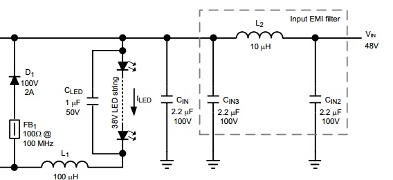
The ferrite bead should go between L1 and D1.

In the circuit below FB1 and CLED were added for radiative EMI.
enter image description here
Source: TPS92511 Datasheet


At high power when the inductor current is continuous, then PWM will simply control the output voltage.

The Mean Well operates at continuous conduction at all currents with very low ripple.


they can be driven with 24V constant voltage, or dimmed with constant current.

Driving a constant voltage strip with CC is not something I would do. The resistors are just wasting power.

CCT and CRI are measured at the test current. If you use a different current they will change. For this reason you should use a CV power supply.

Assuming the strip current is at optimum CRI then your inductor will change the average current.


I do not believe the MC PCB is necessary with mid-powered LEDs. If I drive both strings on Vesta strips at 700 mA they get a little too hot. I also have some Bridelux EB Gen 2 (BXEB-L0560Z-30E2000-C-B3) strips that I can drive at 1400 mA with no heat sink.

I like what you are doing (or attempting to do). It appears the high CRI is a major priority.
I'm okay with 90 CRI and picked up a few Bridgelux Vesta Series Tunable White Linear Strips. While 98 CRI is desirable I'm not wiling to pay 4-5X for it with the VTC strips. Plus the VTC have very low lm/W. The show stopper for me with the VTC is the resistors. I would use 8 LEDs with a 24V as high efficacy mid powered LED rarely exceed 2.9V. I would use Samsung LM301B and use the A1 bin (2.8V-2.9V). I would use an adjustable CV supply (e.g. Mean Well HEP) to adjust the voltage to match the string with the highest Vf.

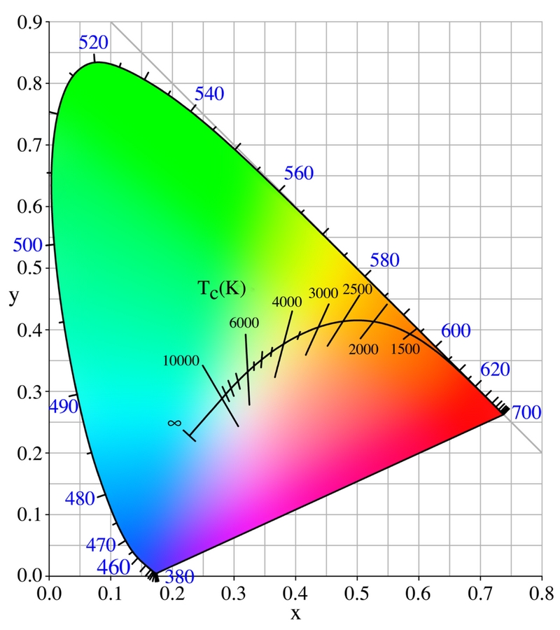
I do not believe that there is a 2200K LED with a CRI above 90. 2200K does not have enough red, 2200K has an orange hue. Notice in the CIE x,y chromaticity space, 2200K is very orange. How do you match an orange LED to natural sun light? Meaningless.
enter image description here
Source: Wikimedia Commons

CRI formulas works best for a CCT of 5000K. At below 4000K and above 6000K CRI becomes meaningless.
Source: A review of colour rendering indices and their application to commercial light sources


24V Red Strip too for extra coziness.

Your 2700K have an R9 of 90+. Adding red will alter both CCT and CRI.

Most "red" strips use LEDs with a wavelength of about 625 nm. This is orange or red/orange depending on the source.

This source from the University of Waikato. The visible spectrum says 630 nm is orange. Wikipedia says:

Red is the color at the end of the visible spectrum of light, next to orange and opposite violet.It has a dominant wavelength of approximately 625–740 nanometres.

My opinion is wavelengths from 645 nm to 700 nm are the RGB equivalent of RGB #FF0000 red so a 660 nm LED would be red and 625 would be orange.
Source: RGB VALUES FOR VISIBLE WAVELENGTHS, Dan Bruton Professor of Physics, Engineering and Astronomy, and Associate Dean of College of Sciences and Mathematics at Stephen F. Austin State University


Orange (aka "red") may not give you that coziness you seek. Orange may make you more alert like a cup of coffee.
Source: Photic memory for executive brain responses

Same applies to your 2200K CCT. HPS street lights are about 2200K. This document In Pursuit of Natural Lighting : How CRI and R Values Measure Light Quality on the subject refers to HPS as

streetlights and other outdoor lighting cast a dead orange glow at night.


Frequency will be between 100 and 250k, not decided yet.

The no-observable-effect level flicker is fFlicker > 3 kHz.
Source: Designing to Mitigate the Effects of Flicker in lED lighting

Why? On one hand you are concerned with EMI on the other you want to generate EMI for some unnecessary reason.

Increasing the output capacitance reduces EMI and the output capacitance is what limits the switching frequency of the FET.

High frequency PWM is used to lower the inductor cost of the buck regulator. You really do not need an inductor with a CV strip.
Source: Effects of High Switching Frequency on Buck Regulators

PWM for dimming should not alter the current.
Source: OSRAM App Note, Dimming InGaN LEDs


Bottom Line

Why not make it easy on yourself and use efficient strips with no resistors (or short yours) and add an LM3409 to your circuit? Use the external parallel FET dimming shown in section 8.3.8 of the datasheet.

Or better yet just use two Mean Well ELG (or HLG) Type B and use its dimming functions.


My solution is to use two of the Bridgelux Vesta (BXEB-TL-2750G-3000-A-13) and two Mean Well HLG-40H-24B Type-B drivers (one for each wavelength) using an Atmel ATtiny417 for controlling the dimming.

I also considered using multiple LM3414HVs with a Mean Well HEP-100-54A CV supply.


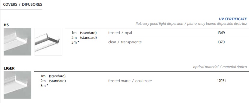
Regarding the aluminum extrusions and diffusers, I could not find an extrusion for a 31 mm strip. But a little over two years ago I contacted Klus to get the transmittance on their enter link description here1369, 17031, and 17111 diffusers.

Considering the best transmittance is 30-70% for a Klus frosted polycarbonate diffuser, I decided not to use diffusers. I mount the strip to an angle bracket and bounce the light off a white surface. The reflectance of a white surface is much better than the transmittance of a polycarbonate diffuser. If needed, I could a a clear strip of polycarbonate with a 95% transmittance for protection of the LEDs.

Answer from Klus:

Please find your answers below. The HS, LIGER etc are just model names:

(HS lightly frosted) 1369- 70%
(LIGER frosted flat) 17031-55% (helps eliminate hot spots from the diodes)
(HS milky round) 17111- 30%
enter image description here

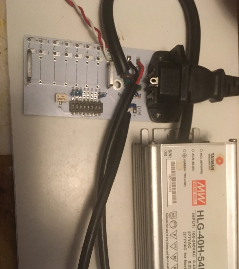
Because it is difficult to find a 2700K 90 CRI and a reasonably priced extrusion that will accommodate a strip with of more than 24 mm, I had designed a 560 mm x 9 mm FR4 strip with 48 LM301B 90 CRI LEDs (1500 lm @ 65 mA - 4000 lm @ 200 mA) to fit in the low cost $15/m ($7/m extrusion + $8/m diffuser) 10 mm Klus Micro ALU B5390ANODA but still use it with just an 1" aluminum angle bracket ($4/m). The angle blocks the LED from direct line of sight and works well as a heatsink.


This strip has 256 dim levels selectable with an 8 position dip switch plus a potentiometer to fine tune to any dim level if necessary. Uses the dim wires on the HLG driver.
enter image description here


9 mm strip mounted to angle bracket

enter image description here


This one 560 mm x 9 mm strip is more than sufficient to read small print anywhere in a 12' x 20' room.
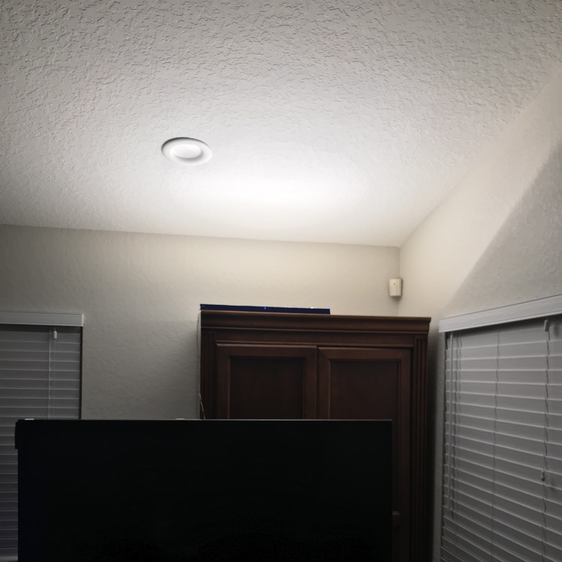
enter image description here


At 1500 lm, this 2700K 90 CRI strip has a typical efficacy of 190 lm/W (33 lm, 2.65 Vf x 65 mA).

Your strip has an efficacy of 58 lm/W (500 lm / 8.6 W).

The Bridgelux Vesta 2700K 90 CRI has an efficacy of 129 lm/W.
The Bridgelux EB Gen2 3000K 80 CRI strips have an efficacy of 175 lm/W.


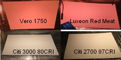
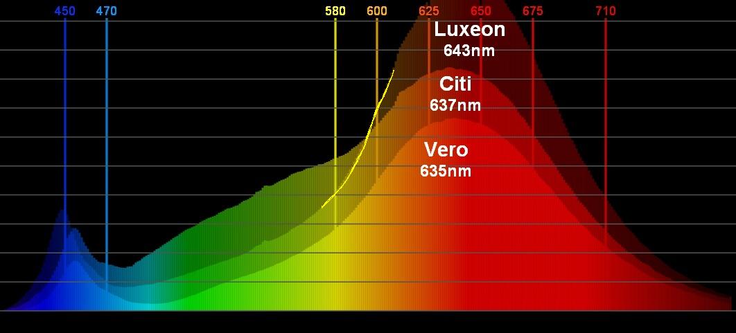
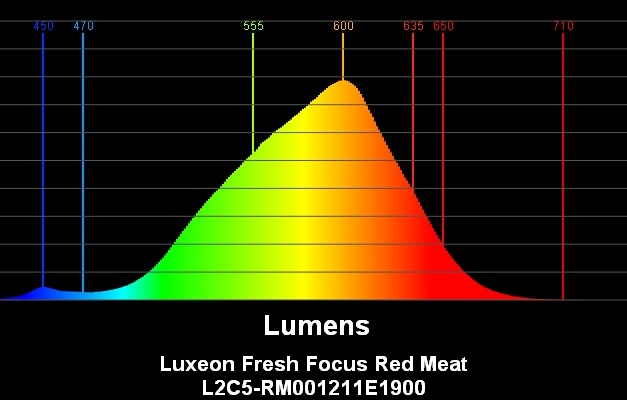
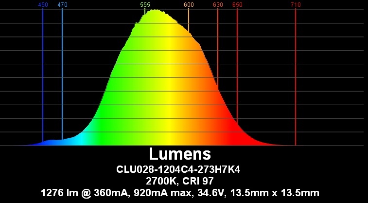
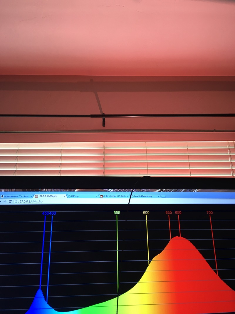
I have used Luxeon Fresh Focus and CrispColor LEDs on this strip. The Fresh Focus has some very "warm" LEDs. The Fresh Focus Red Meat nearly identical to the 1750K 80 CRI Bridgelux Décor Food Meat & Deli. The Fresh Focus Marbled Meat's spectrum has deeper red than the Red Meat.

Color comparison of reflection off bright white paper.
enter image description here


Spectrum in Radiometric Watts (Citi is the 2700K 97 CRI)
enter image description here


Red Meat in Photometric Lumens or Lux
enter image description here


Citi 2700K 97 CRI in Photometric Lumens or Lux
enter image description here


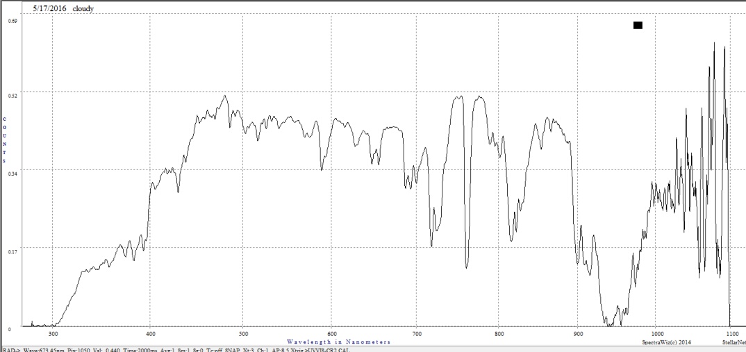
Sunlight on a cloudy day measured with the same StelarNet Blue Wave spectrometer as used for measuring the LED spectrum above. Captured before I wrote the color app used to create the above.

The Y axis is quantum counts (number of photons). This is close to radiometric watts.
enter image description here


This is sunlight in photometric

enter image description here
Source Ultraviolet Photography Forum


Red Meat reflected off white ceiling
enter image description here

\$\endgroup\$
10
  • \$\begingroup\$ Thanks for all the info! I'll need some time to digest all this. I didn't want to make the question too long so I omitted lots of details. The light has been on the ceiling of my living room for about a month now. It is powered by a bench power supply which sits on my coffee table... it's a dual channel supply and I'm using current knobs to set the brightness and color temp. I know varying the current will change the color a bit but in practice I don't find this to be a problem. This isn't a calibrated light for graphics design... \$\endgroup\$
    – bobflux
    Commented Dec 28, 2018 at 12:52
  • \$\begingroup\$ The #1 requirement is: no blue peak. For a while I've been unable to sleep properly, always fell asleep very late. I've read about excess blue light from LEDs screwing up the circadian rhythm. So I picked these Yuji LEDs which use violet chips, not blue, this is relatively new tech hence the terrible lm/W and ridiculously expensive. However... it works, I'm sleeping a lot better now. I also love the excellent CRI, as you say 2700K is not optimum for color rendition, for this I set it to a more neutral white by adjusting the current. \$\endgroup\$
    – bobflux
    Commented Dec 28, 2018 at 13:09
  • \$\begingroup\$ And... since you sound quite interested about LEDs, have you tried variable color temperature? I had doubts before trying it, I mean I read that the CCT that feels "just right" depends on light intensity, time of day, mood, weather, etc but before trying it I kinda dismissed it as new-age woo-woo, but it really works! On overcast days like today, matching the CCT of outdoors light is very pleasant. \$\endgroup\$
    – bobflux
    Commented Dec 28, 2018 at 13:28
  • \$\begingroup\$ I have been working with the University of Florida Horticulture Dept. designing fixtures for photomorphogenesis research with LED spectrum. I am also working on the most efficient and cost effective way for indoor farms to use LEDs. So yes, CCT and CRI are a very important part of my work, hence the red meat LED. I bought the Vesta for a grow light fixture and now may them for kitchen counter lighting. I find 5000K good for eyesight and 2700K for atmosphere. I spent a day or two looking into the blue serotonin research papers and concluded it is BS. \$\endgroup\$ Commented Dec 28, 2018 at 18:37
  • \$\begingroup\$ There were some 5 year studies where two different lenses were implanted in each eye. One with a blue filter. No difference was found. Yes there were studies "proving" blue blocker reading glasses help but they were low quality studies probably faked to sell glasses. The hypothesis was real but disproved in my opinion. Certainly not generally agreed upon by the researchers. It stems from the natural caramelization of the eye's lens with age which then filters blue light. I've had one my lenses replaced and the difference in blue is amazing. \$\endgroup\$ Commented Dec 28, 2018 at 18:51

Your Answer

By clicking “Post Your Answer”, you agree to our terms of service and acknowledge you have read our privacy policy.

Not the answer you're looking for? Browse other questions tagged or ask your own question.