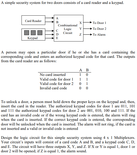
I draw the cicuit without using any MUX. But my project says I need to use 4x1 MUXs and I couldn't find where to use 4x1 MUXs. I tried put MUX of each output but this was very pointless, no need to use 4x1 MUX for the X output. So how do I need to design the circuit using 4x1 MUXs.
1 Answer
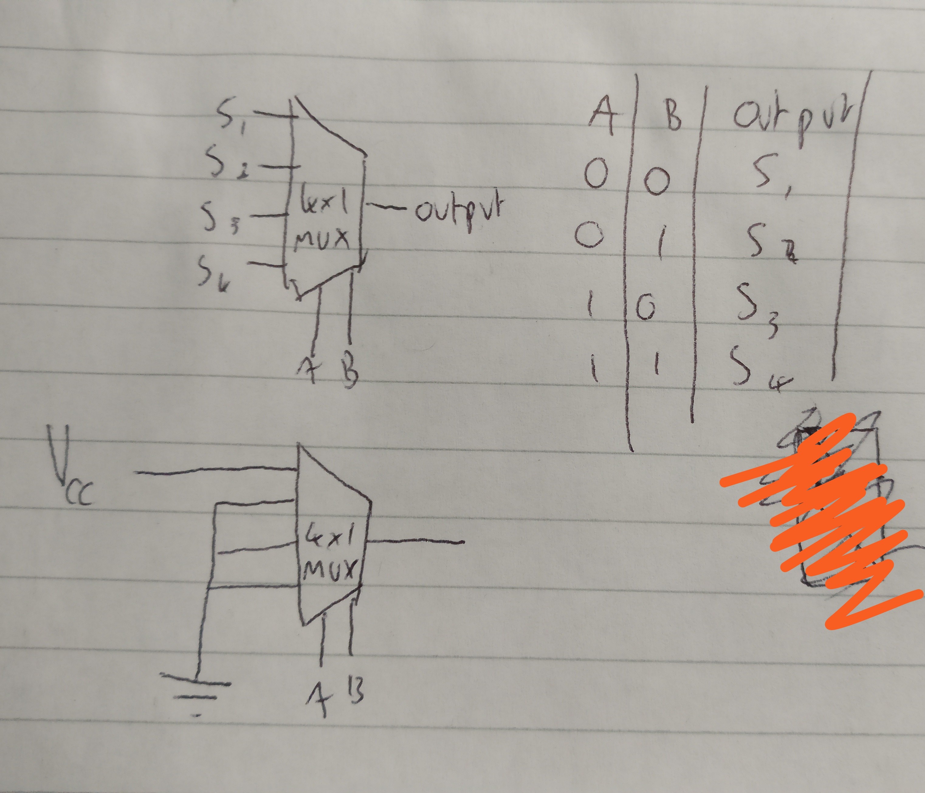
Remember that the combinational logic circuit gives you a 2 bit output, making 4 possible combinations that you have (no card/valid code 1 and 2/invalid code). A 4x1 multiplexer chooses an output from 4 inputs based on a selector input - that is, 2 bits. Ideally you would want to attach the A and B outputs to the MUX inputs - then based on your spec, choose when the output should be on. Then from here, you choose which of the 4 inputs is connected high, and which are grounded.
For e.g., if you want to sound the alarm, then you must make the output 1 for the alarm signal (that is, 0 and 0 for A and B). For that MUX, make the topmost(conventionally) input high, and ground the rest. Then you use 2 other MUX (or maybe 1?) for the doors 1 and 2. Here is an example of the alarm multiplexer, as it only needs to be on for 00 as AB:
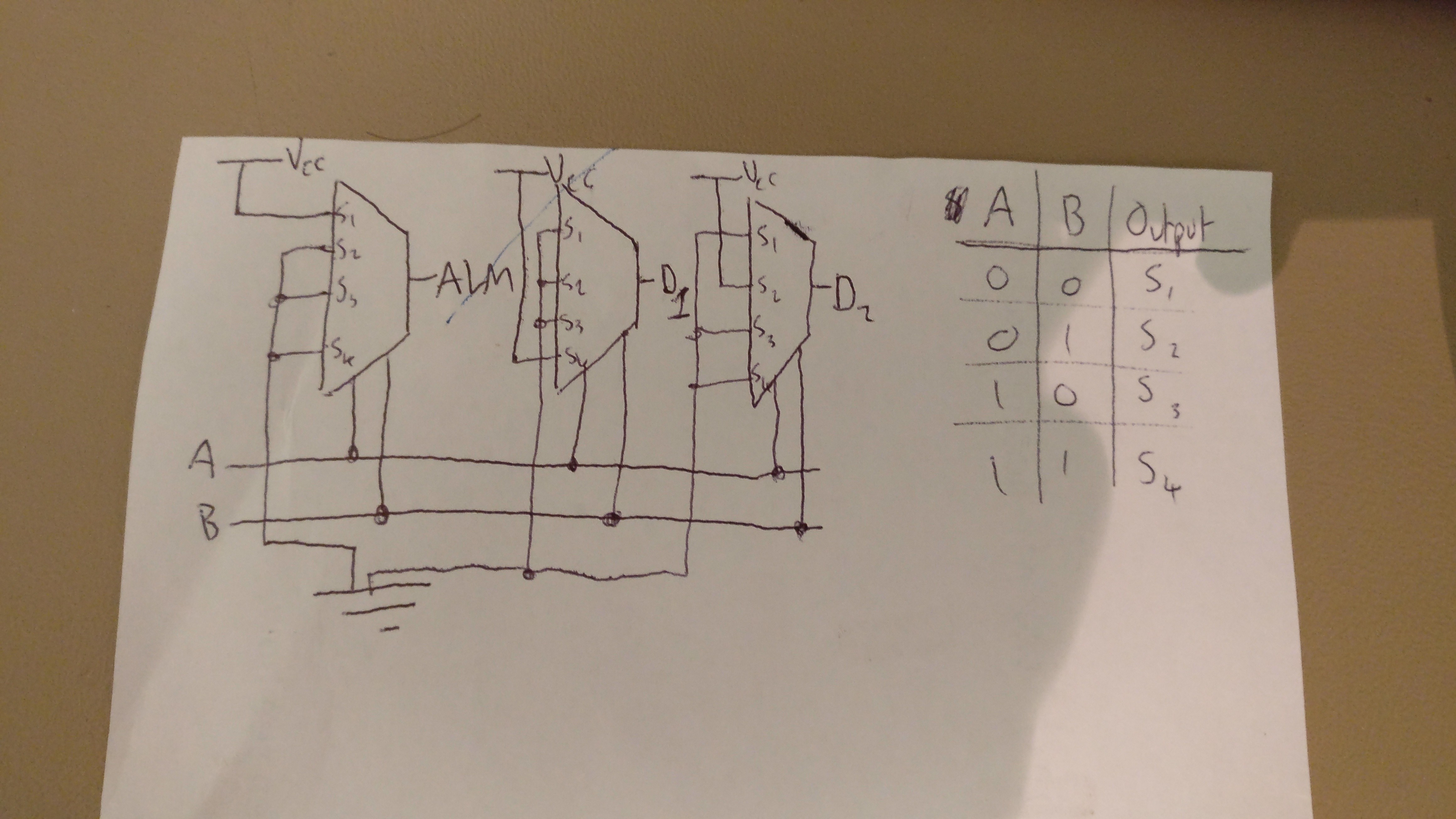
EDIT: Here is a crude solution for the multiplex output for your question, using 3 MUXes. See if you can understand how they all work.
-
\$\begingroup\$ As I understand the task, the alarm should also be ON when wrong keypads are pressed, but valid card is present. For instance if person holds wrong kepayd for door 1 (000) but still uses corect card for door 1 (AB = 11), the alarm should be ON, and door 1 OFF \$\endgroup\$ Commented Dec 29, 2018 at 21:07
-
\$\begingroup\$ Doesn't it say "valid CODE for door 1", implying both the card and correct code have to be in? Only then it will either display 11 or 01 as AB right? \$\endgroup\$ Commented Dec 29, 2018 at 21:17
-
\$\begingroup\$ Well, that obscured me too. But it says in the beginning: "A person may open a particular door if he or she has a card containing the corresponding code AND enters an authorization keypad code". So I read it as card code and keypad code are two different things, and there are separate cards for door 1 and cards for door 2. So AB are only outputs for the card reader. \$\endgroup\$ Commented Dec 29, 2018 at 21:25
-
\$\begingroup\$ Ah, I see there are 2 different codes now. I thought the 000 etc were unique to each card, but apparently each card has its own code. I think there may need to be additional steps to this now. I do still think the approach of using a MUX for each output is the right way, although there needs to be additional circuitry to output the right 2 bits when the correct card and keycode is inserted. \$\endgroup\$ Commented Dec 29, 2018 at 21:31
-
\$\begingroup\$ I think you approach is correct. I actually used it and it took me 11 MUXes to implement full logic. I think it can be made easier. \$\endgroup\$ Commented Dec 29, 2018 at 21:34


