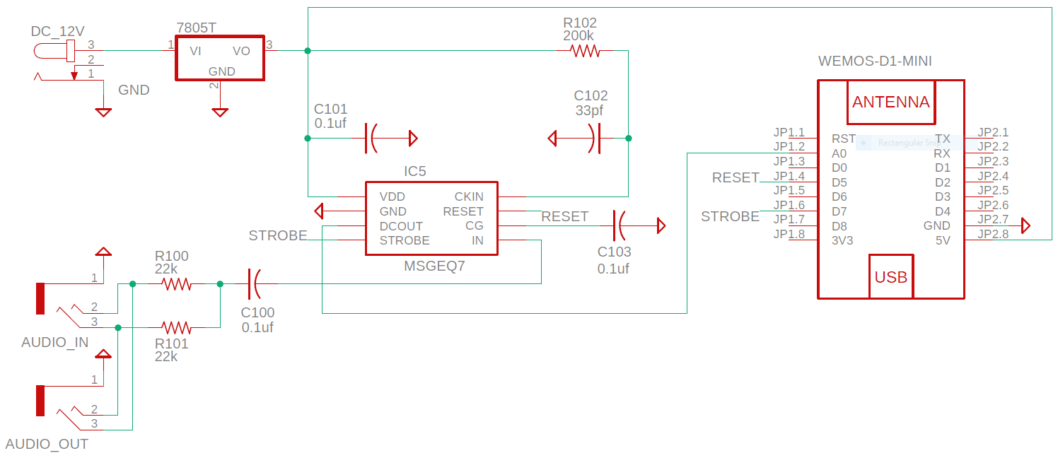
I'm working on a hobby Arduino project to create an audio visualizer using an LED strip. I'm using the MSGEQ7 to separate the signal into 7 bands, then send it to a Wemos D1 Mini. I started by constructing the following schematic based on the typical application diagram as found on the last page of the MSGEQ7 datasheet here
Assembled on a breadboard, it works as expected with a few noise spikes here and there that can probably be filtered out on the software side. Where do these voltage spikes come from? Originally, I wanted to forego the DC jack and power the MSGEQ7 from the 5V pin on the Wemos (with the Wemos powered via USB), however, if I remember correctly, powering it via a DC jack/12V wall-wart + 7805 5V regulator resulted in less of these voltage spikes.
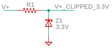
I want to protect the A0 input that's rated at 3.3V max, and research online has led me to what I believe is called a Zener clipper pictured below.
Should I protect the analog input or does this seem like over engineering? How do I decide on the value of R1?
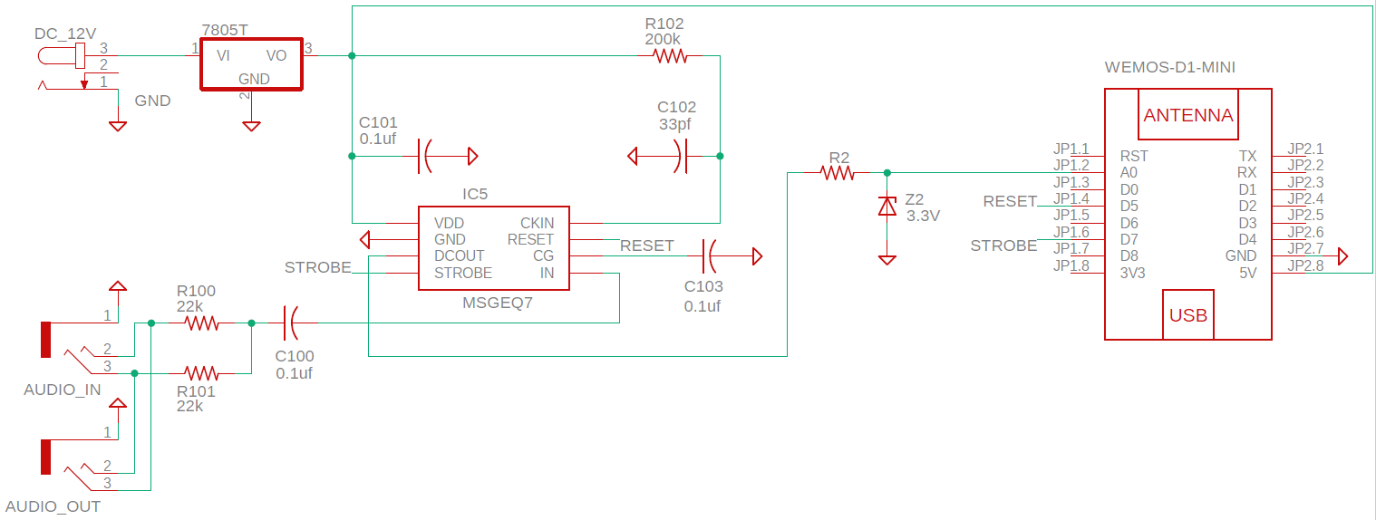
Here's the final schematic after working in the clipper.
The frequency of the noise spikes increased a bit after adding this clipper (I arbitrarily used a 56 ohm resistor for R1), it still seems like it could be filtered out software side, but am I somehow able to reduce these spikes by redesigning the circuit?


