2
\$\begingroup\$

Is there a good way to monitor a CR2032 coin cell's voltage, that does not load it down when other power is off?

We are using a CR2032 coin cell for a battery-backed real-time clock. When main power is on, I want the (ARM) processor to measure the coin cell voltage to within 100mV or better to detect a 'coin cell failure' condition. ADC channels are available.

When main power is off, the average measurement circuit loading must not exceed 1uA to avoid discharging the coin cell, and the measurement circuit must not charge the cell.

Desired coin cell lifetime is 10 years. Typical draw is currently 1.2uA, which uses 105mAh of the 240mAh capacity. Aging eats another 10%. Component variations, higher temperature and humidity, any board contamination may cause earlier failure.

Hoping for something fairly compact and inexpensive.

Edit: there is not enough room for a relay.

\$\endgroup\$
2
  • 1
    \$\begingroup\$ You could consider building whatever you build to "measure on request" in addition to using a high impedance measurement input. You could probably get away just fine with 5 or 30 minutes between measurements, and if the measurement is fast enough your power consumption could be negligible. \$\endgroup\$
    – K H
    Commented Jan 11, 2019 at 1:22
  • \$\begingroup\$ @KH I agree with "measure on request", the interval could be on the order of days. It's the compact (no relays), don't drain the battery with other power off, inexpensive part that is giving me trouble. \$\endgroup\$ Commented Jan 11, 2019 at 1:31

3 Answers 3

2
\$\begingroup\$

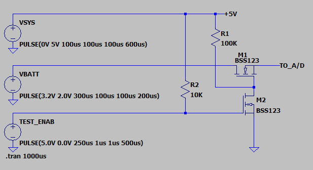
Here is how I have previously designed the circuit to isolate a coin cell from a microcontroller A/D circuit. I modeled this in LTSpice so it should be easy for you to evaluate and see that the load on the battery when the test mode is OFF is very very small.

enter image description here

Note that the BSS123 may not be the most ideal NFET for this isolation circuit because its threshold voltage gets close to the delta between the +5V supply and the highest level of the coin cell voltage. You may want to select an NFET that has a guaranteed 1.5V threshold.

It is possible to get dual NFETs in one very small 6-pin SMT package so board space is not a problem with this circuit.

Some times it can give a better status of the coin cell to load the cell some during the duration of the testing. This can be accommodated by placing a resistor from the M1 drain to GND. For a 3V coin cell a 1Meg resistor would place a load of 3uA on the battery. Testing should be scheduled to only be done once a week or so to that the testing itself does not significantly reduce the battery life.

In more recent designs I have moved away from this technique of measuring the battery. Instead I use an I2C RTC chip. The battery attaches to that and the RTC chip provides a check that the battery has not gone below a critical warning threshold. This type of RTC chip also nicely provides a very low current way to maintain a clock/calendar and is far superior to trying to use the battery backed clocks that are on many MCUs. The battery switching circuits and MCU power gating for sleep modes are never quite as good as the low current draw that a good RTC chip can provide.

\$\endgroup\$
1
  • \$\begingroup\$ I appreciate the circuit and advice! I'm curious about what I2C RTC chip you like. \$\endgroup\$ Commented Jan 22, 2019 at 1:45
0
\$\begingroup\$

It's always going to require a bit of power to take a measurement. However, you can take your measurements periodically, instead of continuously, to save a lot of energy. For instance, if you were measuring the cell voltage with a micro's ADC, you could use one of the micro's pins as your voltage source, and therefore have the ability to tristate it or set it low between measurements, so there is zero current between reads. You could then run it through a voltage divider before measuring it against a fixed voltage reference. In between measurements, the fixed voltage reference and ADC can be turned off. So while taking a reading, your ADC, voltage reference, and voltage divider are all burning power. But after your measurement, the power requirements can be reduced considerably.

\$\endgroup\$
1
  • 1
    \$\begingroup\$ With power off to the microcontroller, the 3V coin cell will discharge through the ESD protection diodes of the micro's input pins and attempt to power the circuit. To limit this to the target 1uA, a 3 Megohm series resistor would be required. Not sure how good of an ADC reading I can get through a 3 Megohm resistor. \$\endgroup\$ Commented Jan 11, 2019 at 1:35
0
\$\begingroup\$

You can use solid state relay to connect/disconnect battery voltage and measure when it is needed. This is to ensure no leakage of battery voltage and affecting battery life.

\$\endgroup\$
1
  • 1
    \$\begingroup\$ It may be educational to attempt to select such a relay, including checking leakage current vs. normal draw ("Typical draw is currently 1.2uA"), drive requirements, price, size, etc. \$\endgroup\$ Commented Nov 6 at 2:31

Your Answer

By clicking “Post Your Answer”, you agree to our terms of service and acknowledge you have read our privacy policy.

Not the answer you're looking for? Browse other questions tagged or ask your own question.