0
\$\begingroup\$

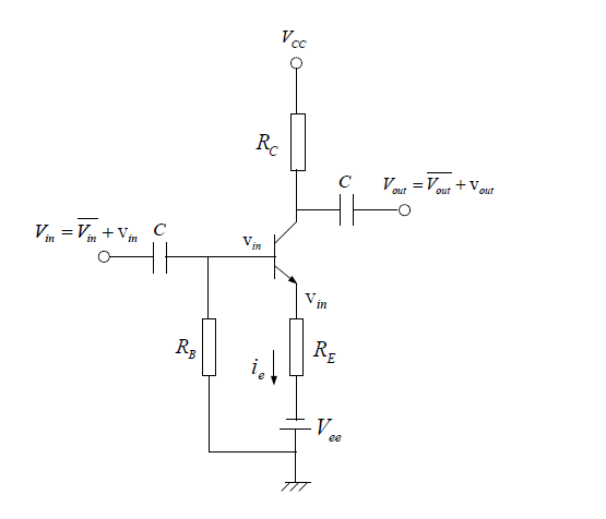
Suppose you have the circuit: enter image description here

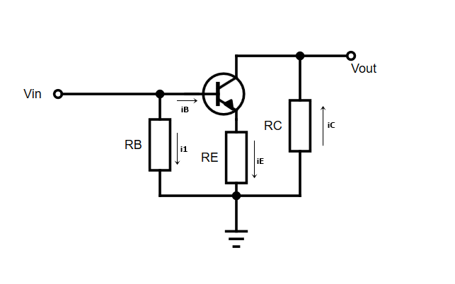
For an AC analysis we can draw the following circuit: enter image description here

Now my job is to find \$v_{out}\$, which can be easily found by: $$ i_E=\frac{v_{in}}{R_E} \\ i_C=-\frac{v_{out}}{R_C} \\ i_E=i_C \\ v_{out}=-\frac{R_C}{R_E} v_{in} $$

And this is reasonable, but one could also argue: $$ i_B=-i_1 \\ i_B=\frac{i_C}{\beta} \\ i_C=-\frac{v_{out}}{R_C} \\ i_1=\frac{v_{in}}{R_B} \\ v_{out}=\beta \frac{R_C}{R_B} v_{in} $$

The second one I think is wrong but I can't find the loophole in the reasoning.

\$\endgroup\$
3
  • \$\begingroup\$ Where's the contradiction you're asking about? \$\endgroup\$
    – Chu
    Commented Jan 11, 2019 at 1:30
  • \$\begingroup\$ It is already edited, I was having some troubles with the formating and posted it earlier than I was supposed to \$\endgroup\$
    – Bidon
    Commented Jan 11, 2019 at 1:33
  • \$\begingroup\$ 2 cents: first would need to analyze bias network to establish Q point and on top of that do a small signal analysis where the BJT is modeled as a resistor like Rahul said (when BJT is at the Q point, it looks like a resistor to the small AC signal on top of the large Q point signal). The Q point is in the active region, and the movement from the Q point by the small signal is small enough that it remains active as opposed to saturated or cutoff. Allan Hambley has good discussion of this in Electrical Engineering: Principles & Applications (6th Edition) chapter 13. \$\endgroup\$
    – Daniel
    Commented Jan 11, 2019 at 4:29

1 Answer 1

2
\$\begingroup\$

There is a problem with the first set of equations that you present: \$ i_E \$ is not equal to \$ \frac{V_{in}}{R_E} \$, and \$ i_E \$ is not equal to \$ i_C \$. For a transistor in forward-active operation, these two statements are not true, either in DC or AC analysis. When you do AC analysis, you can use the hybrid-\$\pi\$ model. The hybrid-\$\pi\$ model turns your BJT into an equivalent network consisting of two resistors and a current source. The characteristic parameters associated with the model are \$ R_{\pi} \$ , \$ R_o \$, and \$ g_m \$, which are small signal impedances and transconductance respectively.

$$ r_{\pi} = \frac{V_T}{I_{BQ}} $$ $$ g_m = \frac{I_{CQ}}{V_T} = \frac{\beta}{r_{\pi}} $$ $$ r_o= \frac{V_A}{I_{CQ}} $$

Where \$ I_{BQ} \$ and \$ I_{CQ} \$ are the DC (quiescent) currents through the amplifier.

Let's work through the analysis of your amplifier.
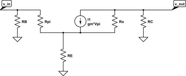
schematic

simulate this circuit – Schematic created using CircuitLab

To simplify the analysis while introducing this model, I'm going to ignore \$ R_o \$ which is allowed because \$ R_o \$ depends on the Early voltage, which is usually pretty large.

Applying a voltage at v_in, get the following expressions:

$$ V_{\pi}\equiv I_Br_{\pi} $$ $$ I_E = I_B + g_mV_{\pi} $$ $$ V_{\pi} = V_{in} - I_ER_E = V_{in} - \left(I_B + g_mV_{\pi}\right)R_E $$ $$ \therefore V_{in} = I_B \left(r_{\pi} + (1 + g_mr_{\pi})R_E\right) $$ $$ \therefore V_{\pi} = V_{in} \cdot \frac{r_{\pi}}{r_{\pi} + (1 + g_mr_{\pi})R_E} $$ $$ V_{out} = -R_C\cdot g_mV_{\pi} $$

With substitution, you can express \$ V_{out} \$ as a function of \$ V_{in} \$ and the characteristic parameters, giving you the voltage gain as $$ A_v \equiv \frac{V_{out}}{V_{in}} = -\frac{r_{\pi}}{r_{\pi} + (1 + g_mr_{\pi})R_E} \cdot g_mR_C $$

With some substitution, you can also express the gain of the amplifier in a more compact (and common) form:

$$ A_v = -\frac{r_{\pi}}{r_{\pi} + (1 + \beta)R_E}\cdot g_mR_C $$
\$\endgroup\$
5
  • \$\begingroup\$ I'm really new to all of this, and very little of transistor equivalent models, but you mention thet \$i_C \neq i_E \$, however, \$i_b+i_C=i_E\$ and \$ i_C=\beta i_B \$ thus \$(\beta +1)i_B=i_E \$ and if \$\beta>>1 \$, then \$i_E \approx i_C \$, shouldn't it? It's not exactly equal but it's a very close approximation \$\endgroup\$
    – Bidon
    Commented Jan 11, 2019 at 16:16
  • \$\begingroup\$ Yes - of course. Hence, in the last expression you can set (1+beta)=beta. Using the known relation beta/rpi=gm (transconductance), the last expression simplifies to Av=-gmRc/(1+gmRc). This form is very interesting and easy to verify since it is in full accordance with control theory (feedback theory), which says: A(closed loop)=Acl=Aol/(1+LG) with open-loop gain Aol (without feedback) and LG=loop gain. \$\endgroup\$
    – LvW
    Commented Jan 11, 2019 at 16:46
  • 1
    \$\begingroup\$ @Bidon yes. In many cases, I_c and I_e can be equated as approximately equal, since BJT beta is usually very large. However, I wanted to keep the gain equation as generic as possible. For large beta, the equation becomes A_v = -gmRc/(1+gmRe) \$\endgroup\$
    – Rahul Iyer
    Commented Jan 11, 2019 at 18:07
  • \$\begingroup\$ @RahulIyer Given that I have 0 knowledge of the general case, only the ideal case, what would you say is the flaw in my reasoning, and why is the second set of equations wrong and the first one correct? \$\endgroup\$
    – Bidon
    Commented Jan 11, 2019 at 21:44
  • 1
    \$\begingroup\$ @Bidon I'ts not about general vs. ideal cases. I chose to introduce the most general form of the equation possible, which is derived from the working principles of the BJT as a small-signal amplifier. You can make simplifications such as beta + 1 = beta if they are reasonable given the actual value of beta for your design. I believe the error in your analysis comes from I_B = I_1. Look at the model that I posted, and you'll see that the base resistor R_B does not show up, which makes sense because the small-signal base current should only be a function of the small signal AC input voltage. \$\endgroup\$
    – Rahul Iyer
    Commented Jan 11, 2019 at 22:14

Your Answer

By clicking “Post Your Answer”, you agree to our terms of service and acknowledge you have read our privacy policy.

Not the answer you're looking for? Browse other questions tagged or ask your own question.