1
\$\begingroup\$

I am using a lot of these types of isolated DCDC converters for measurement circuits.

The problem is they introduce so much switching noise. I try to put filters on the output and even put the recommended 220 µH and 0.22 µF filter on from that datasheet but the noise is always there!

How do I get rid of noise from this type of DCDC? It is really annoying. There is always this short period of ringing and oscillation happening at like 50 kHz or 100 kHz (presumably at the switching frequency of that particular DCDC) of up to 20mV sometimes and this destroys my measurements unless I take averages.

DCDCs like these ones are even more noise, 100mVp-p!

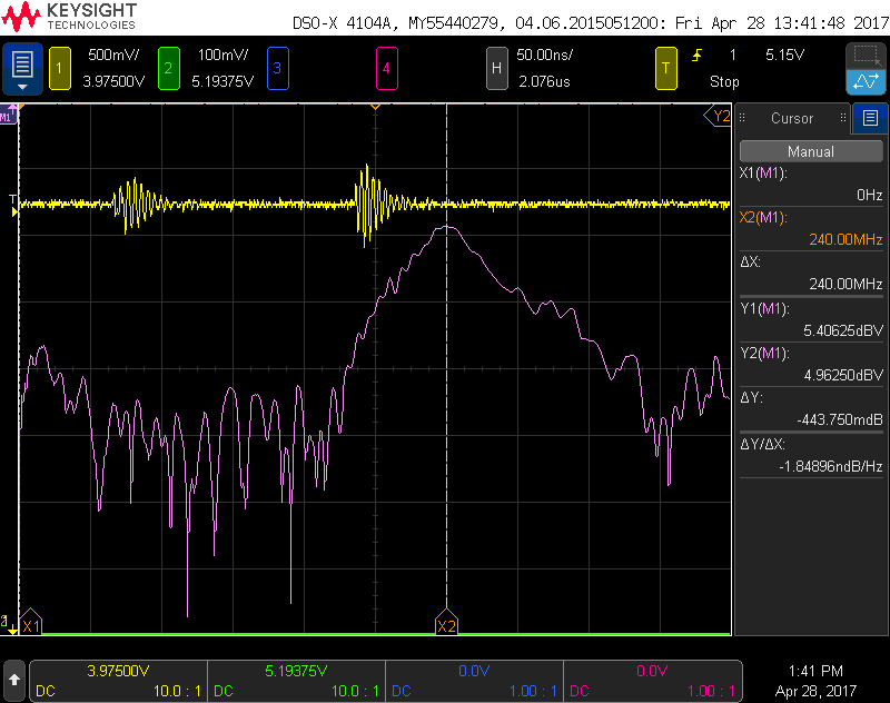
Noise looks like the yellow waveform here (not my image): enter image description here

\$\endgroup\$
9
  • \$\begingroup\$ Do you have a scope capture of the noise with frequency measurements? What do you mean by "short period of ringing"? EDIT: From the datasheet, the converters have 10-20mV pk-pk ripple depending on which PN you got. What is this "measurement circuit" you're talking about? Perhaps the problem lies there. \$\endgroup\$
    – Stiddily
    Commented Jan 16, 2019 at 14:32
  • \$\begingroup\$ LIke the yellow waveform here: i.sstatic.net/bI5DQ.png \$\endgroup\$
    – AQUAMAN
    Commented Jan 16, 2019 at 14:36
  • 1
    \$\begingroup\$ Measurement circuit is just some op amps and an ADC. The noise from these converters ends up everywhere in the circuit \$\endgroup\$
    – AQUAMAN
    Commented Jan 16, 2019 at 14:40
  • \$\begingroup\$ Can I see the circuit? It could be the opamps locking onto the ripple and amplifying it. \$\endgroup\$
    – Stiddily
    Commented Jan 16, 2019 at 14:42
  • 1
    \$\begingroup\$ Noise can be CM or DM or both and must be examined from both input and outputs using proper *balanced differential probe methods with <1pF loads or AC coupled into 50 Ohm terminated coax. to eliminate EMI measurement errors. Once the cause-effects spectrum are seen and relevant spurious zones and spectral impedances are known then the interactions of LC & ESR isolation & suppression etc then a solution can be managed swiftly. Until then it is trial and error. \$\endgroup\$
    – D.A.S.
    Commented Apr 13, 2019 at 1:23

1 Answer 1

2
\$\begingroup\$

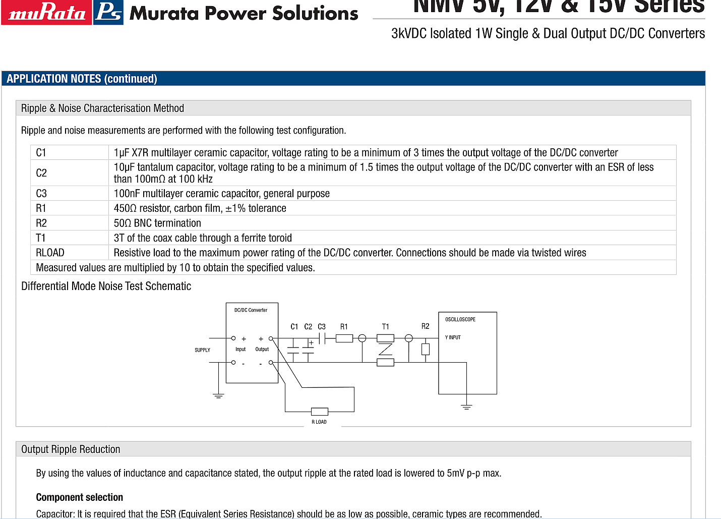
1st one must follow the datasheet Test methods for proper noise measurement.

C1,C2 supplement the ripple rejection to meet specs under the conditions given.

C3 and R1 present a 500 Ohm load impedance with R2 (50 Ohm) to reduce the level 10:1.

T1 is a common-mode choke made of 3 turns of coax cable thru a ferrite torroid to raise the CM "Transfer Impedance" of coax where some types are better at shielding UHF better than others.
enter image description here

Then Output Ripple Reduction guidelines are also stated in the datasheet about ESR.

Note that "general purpose" electrolytic caps have an ESR *C time constant in the range of 200us which is far too high while low ESR caps are in the 1us range.

To reduce noise above this BW of 350kHz which is well above the regulator loop regulator bandwidth, one must use film or low ESR type ceramic SMD caps with rated ESR or S parameters and again not cheap no-spec any old ceramic caps.

Parameters of importance in traces, capacitors and inductive power leads are all derived from low ratios of path length to width ratio or L/W ratio. This is in order to reduce series inductance or ESL and raise path capacitance to ground.

The RLC Q factor that controls resonant gain from impulse loads is based on the ratio of X(f) /R = Qs and R/X(f)=Qp for series and parallel resonance respectively. Thus very high L/C switched loads require a computed series R to control the Q factor to minimize it without excessive R losses.

Decoupling step loads from the source to reduce ripple requires awareness this RLC equivalent circuit and the step response, the radiation loop area of interference, and load regulation effects on the supply.

The regulator can often only regulate noise up to 50kHz and relies on the brute force low ESR caps to absorb load transients above this frequency.

Final Reminder

Just remember the Test Engineer methods shown above are the best practice needed to ensure error capturing the DC + AC ripple power signals avoid false measurements.

When not readily available even a good 10:1 prove with no ground leads using only tip and ring may do for a start and wrap the coax into a coil with clamshell snap ferrite CM choke will improve accuracy of results with < 20ns rise times.

\$\endgroup\$

Your Answer

By clicking “Post Your Answer”, you agree to our terms of service and acknowledge you have read our privacy policy.

Not the answer you're looking for? Browse other questions tagged or ask your own question.