0
\$\begingroup\$

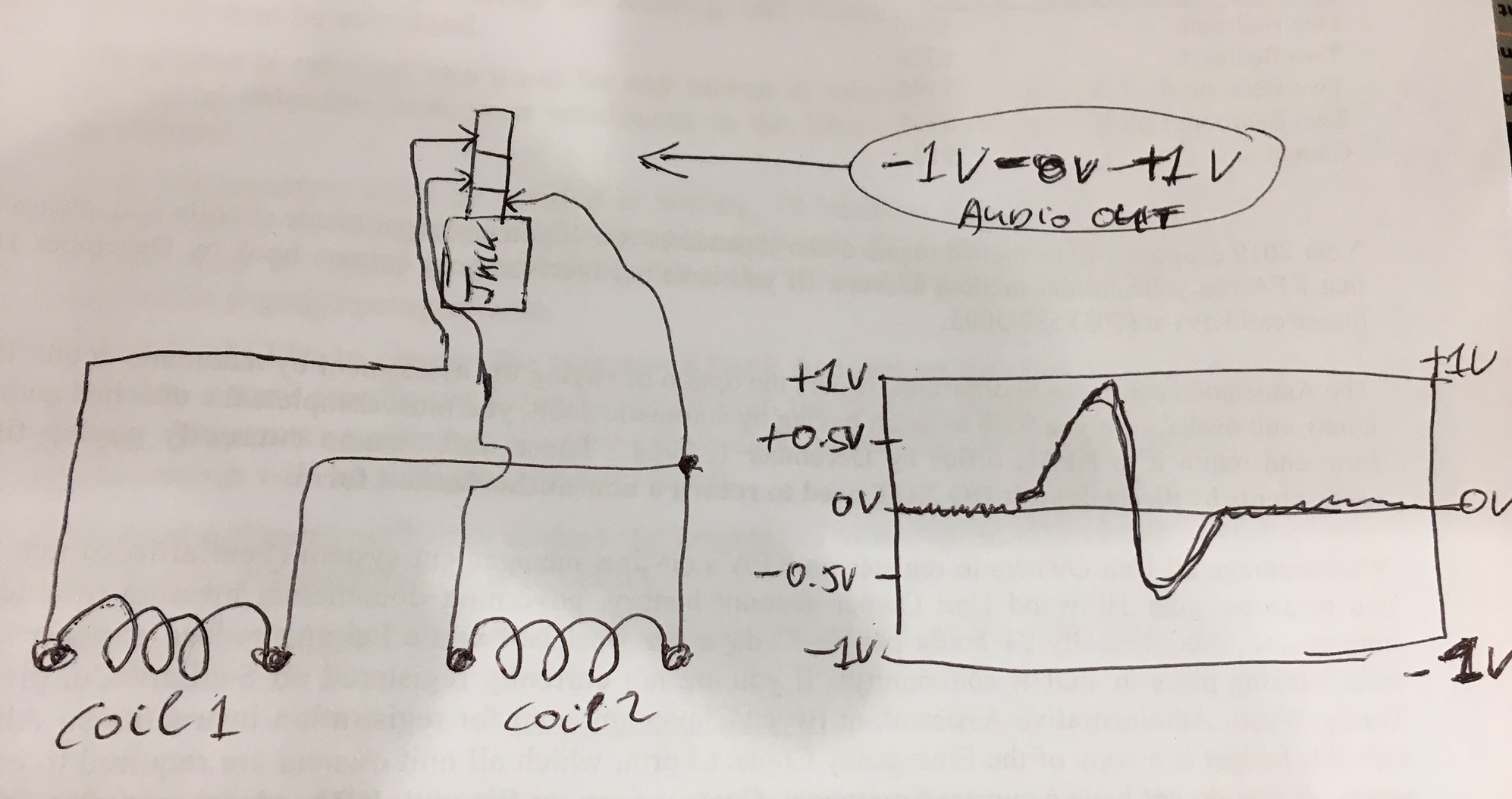
Would like to interface two passive magnetic-inductance sensors output (audio-level signal) with Arduino. The sensor circuit comprises of two wire-wound sensors and has no power. It generates it's own voltage when eddy currents are created by a nearby object passing by. The two sensors have a stereo audio jack with a common ground. When connected to a laptop mic-port (3.7V power) and read by Audacity the signal is centered at zero volts resting. When an object creates eddy-currents the signal is a nice AC sinus wave from 0V to 1V peak and down to -0.75V peak and back up to the zero volt line. (actually two sinus waves one after another, but illustrated here only one)

I would like to make a digital HIGH and LOW signal from the AC audio level (-1V to 1V centered at 0V) sensor output that Arduino can read on a digital pin.

The other option is to have Arduino read the sensor value on one analog pin with the INTERNAL voltage reference set at 1.1V.

I know that Arduino cannot have more than 0.3V negative voltage going to it and cannot exceed 5V either. What would be the best way to proceed? How can I condition/amplify the AC eddy-current audio-signal(s) into a reliable digital HIGH? I do not need any audio, just want to detect the HIGH. Or how can I condition the signal(s) into an analog value that the analog-in pin can read? Thank you for any advice.Here is the passive inductive sensor circuit with the audio-out stereo jack
\$\endgroup\$
2
  • \$\begingroup\$ So if the object is MOVING, the two outputs will have non-zero voltages? \$\endgroup\$ Commented Jan 19, 2019 at 8:07
  • \$\begingroup\$ Yes,the fast moving metal object creates about 31ms pulse AC eddy currents in the coils, which happens to be about -0.75V to +1V peak to peak when measured with Audacity using the powered (3.7V) mic port of a laptop. However, when I power the two sensor coils with 3.7V from arduino's power supply and feed their inputs to Analog0 pin, the changes are almost undetectable. Common ground of the two coils are tied to arduino's ground. Added a capacitor in-line with Analog0-in, did a 2.2K resistor to the ground also from Analog0 input pin...but the signal does not change. Signal is @10 mV resting. \$\endgroup\$
    – TommyS
    Commented Jan 19, 2019 at 8:32

2 Answers 2

1
\$\begingroup\$

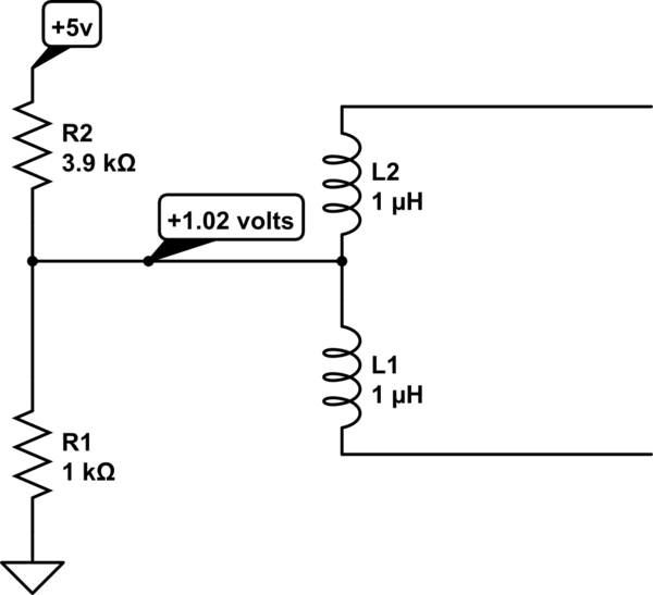
You could interface like this

schematic

simulate this circuit – Schematic created using CircuitLab

\$\endgroup\$
3
  • \$\begingroup\$ Thank you very much, set up circuit with the common line (normally the Ground) between the two coils going to to the voltage divider resistors (3.9K/1K). Connected other side of both coils to Arduino Nano's Analog0 pin. Getting 0.975V to Analog0 and reading 209/210/211 values on the 0-1024 scale.But when I triggered the two coils the analogRead values didn'y change.Using 38400baud serial terminal and printLn without delay in code. Expecting two positive spikes of at least 0.8-1V amplitude each about 31ms apart just like when I plug it in the laptop mic-in port.Need DC block capacitor/diode? \$\endgroup\$
    – TommyS
    Commented Jan 21, 2019 at 12:41
  • \$\begingroup\$ I suspect that the analog input trigger-signal has too high of a frequency for Arduino to detect. The signal I am measuring comprises of two separate 5-8ms wide positive sine wave peaks 31 ms apart with 0.9V amplitude when measured with Audacity at 44100 HZ sampling. I read there is a way to code up to 38KHZ sampling, but I will try two digital interrupt pins instead with amplified peaks to digital HIGH amplitude. \$\endgroup\$
    – TommyS
    Commented Jan 22, 2019 at 23:29
  • \$\begingroup\$ The voltage interface suggested is correct. But the signal has to have apmlification even if peak below 1V because the chnages are mV range. \$\endgroup\$
    – TommyS
    Commented Apr 24, 2020 at 0:49
0
\$\begingroup\$

The interface can be accomplished with a simple op amp in the non-inverting configuration with a gain of approx. 1000. Op Amp should be a GBW product applicable to the frequency to be captured, in this case over 3 MHz. The suggested answer above helps to add a DC bias for proper expected signal interface.

\$\endgroup\$

Your Answer

By clicking “Post Your Answer”, you agree to our terms of service and acknowledge you have read our privacy policy.

Not the answer you're looking for? Browse other questions tagged or ask your own question.