1
\$\begingroup\$

I'm trying to connect a Solid state relay using Arduino Nano. I have a push button on the circuit when press, turn on a water pump (1.5hp).

I was able to make the circuit and code for the push button to supply DC for the SSR input and on uploading, the SSR internal LED turns on when supply voltage is given from arduino.

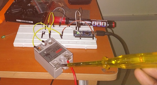
But the strange thing is when I connect the main line to AC in of the SSR I checked the continuity from both terminals, it says no continuity at all. But for some reason I tested the other terminal using a Tester as in the below picture it turns on which means there is current flowing from 1 to 2 without DC input. But why no continuity even then? Also when input DC given nothing happens on AC out terminal..

enter image description here

What I did wrong or Relay is damaged??

\$\endgroup\$

1 Answer 1

3
\$\begingroup\$

when I connect the main line to AC in of the SSR I checked the continuity from both terminals, it says no continuity at all.

You cannot test a solid state relay with Multi-meter. these devices require a minimum amount of voltage/current across the input before the output device will conduct. Most multimeters are designed to simply provide a small amount of voltage in order to measure the ensuing current draw. Therefore, when measuring a solid-state device, the meter will typically report an open circuit (or very high impedance) because it cannot put out enough to turn on the relay.

Please follow this link for more details

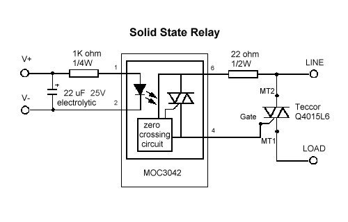
the image below is the schematic of an solid state relay. The triac in the solid state relay is going to turn-on and off when there is supply and load connected across it. then only the driver will work.

In order to keep the traic in on-state after gate trigger there needs to be minimum holding current to be present.

enter image description here

Image source: https://www.galco.com/comp/prod/relay.htm

But for some reason I tested the other terminal using a Tester as in the below picture it turns on which means there is current flowing from 1 to 2 without DC input. But why no continuity even then?

this is due to leakage currents.

\$\endgroup\$
7
  • 1
    \$\begingroup\$ And those leakage currents can hurt if you assume that just because it is "off" you can handle the wires carelessly. Been there and done that. \$\endgroup\$ Commented Jan 20, 2019 at 17:57
  • \$\begingroup\$ Sorry.. So you think the SSR is faulty.. I mean since you pointed leakage current. But still I didnt understand if there is leakage multimeter should show continuity.. isnt it? Why its not showing any connection between terminals even tester blinks?? \$\endgroup\$ Commented Jan 20, 2019 at 18:16
  • \$\begingroup\$ No the scr is not faulty.. the multimeter is unable to make the device to conduct.. don't think about an SSR like a normal relay. And the leakage current are very very low. Pls follow the paper I shared in my answe.. which is very informative. \$\endgroup\$
    – Electron
    Commented Jan 20, 2019 at 18:18
  • \$\begingroup\$ @Electron I just checked the leakage current in my 230v line for the 2 SSRs I have got in hand. Means output terminal to power neutral line. It shows 230v itself.. It looks like the current is flowing without any lose from Input Terminal to output terminal without input COIL voltage (only used the word coil voltage to express the input DC voltage). Does SSR are normally closed?? \$\endgroup\$ Commented Jan 20, 2019 at 18:24
  • \$\begingroup\$ Basically SSR's are normally open devices... test the voltages by connecting a simple lamp load.. you will get clarity. \$\endgroup\$
    – Electron
    Commented Jan 20, 2019 at 18:30

Your Answer

By clicking “Post Your Answer”, you agree to our terms of service and acknowledge you have read our privacy policy.

Not the answer you're looking for? Browse other questions tagged or ask your own question.