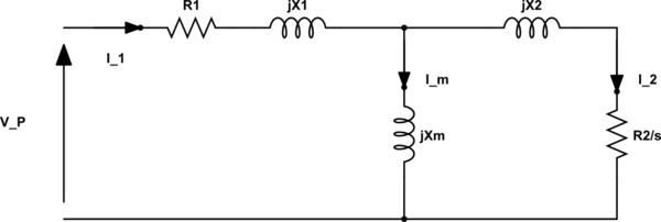
I'm currently trying to model a simplified circuit of an inverter + 3 phase induction motor. For now, I want to represent the DC link as an ideal independent voltage source. To keep this example simple, I also want to keep frequency and input voltage the same, though I expect to be changing these to simulate a VFD
I'm using https://myelectrical.com/notes/entryid/251/induction-motor-equivalent-circuit as reference
The output I want is motor torque and resulting current on the DC link.
So, given \$V_{DC}\$, what would \$I_{DC}\$ be in terms of inverter equations and induction motor equations?
I think I'm most of the way there, but I can't find a full set of equations for this, only separate equations for motors and inverters.

simulate this circuit – Schematic created using CircuitLab
For input voltage to the motor, I think this is correct $$V_{L} = \frac{3}{\sqrt{2}\pi}V_{DC}\\ V_{P} = \frac{V_{L}}{\sqrt{3}}$$ It's my understanding that torque is per phase $$T = \frac{1}{2\pi n_s}\frac{R_{2}}{s}\frac{E_{2}^2}{\frac{R_{2}}{s}^2+X_{2}^2}$$ So total motor torque $$T_{3\phi} = 3T = \frac{3}{2\pi n_s}\frac{R_{2}}{s}\frac{E_{2}^2}{\frac{R_{2}}{s}^2+X_{2}^2}$$ To calculate back emf \$E_2\$: $$E_{2} = V_{P}-\frac{I_{1}}{Z_{1}}$$ Impedance per phase: $$Z_1=R_{1} + jX_{1}\\ Z_m=jX_{m}\\ Z_2=\frac{R_{2}}{s} + jX_{2}\\ Z=Z_{1}+\frac{Z_{m}Z_{2}}{Z_{m}+Z_{2}}$$ Would the calculation back to \$I_{DC}\$ be as follows? $$I_{1} = \frac{V_{P}}{Z}$$ $$I_{L} = \frac{I_{1}}{\sqrt{3}}$$ $$I_{DC} = \frac{3}{\sqrt{2}\pi}I_{L}$$
EDIT: Specifically, I want to know if the equations I have above are correct for determining the average current on the DC link (neglecting most losses for now)
