0
\$\begingroup\$

I have a basic CNC machine for cutting EPS foam which uses about 9.5in/23.5cm long straight 28 gauge Nichrome wire as the cutting element. The nichrome wire is powered independently with a 220V-36V 5A rated step down transformer with a dimmer in series on the mains side. The CNC have no way of knowing the temperature of the wire.

Using this calculator, I found that I needed 5.2V at 1.6A (8.4W) to heat the wire at 600F/316C which is the recommended cutting temperature. But from my experience I found that supplying 2.5V - 3V AC (measuring across the wire with a cheap multimeter) is about right for cutting the foams. I am unable to measure the current or temperature while heating as I do not have the tools for those. Below are a few statistics of voltage and resistivity of the wire:

ACVoltageAcrossWire    WireResistance    Temperature
  0V                      2 Ohm             Cold
2.5V-3V                 30-90 Ohm           Good
  4V                   200-400 Ohm         Glowing

The problem with this setup is that - in my place, mains power is fluctuating very much causing the wire to unevenly heat up during cutting and is almost impossible to control with the dimmer as the machine is moving at 700 - 1000 mm/s. During a single cut, sometimes the wire would heat up too high that it eats up too much of the foam; and then the wire would be too cool that it would start dragging the foam causing lots of wastage.

I tried using a 12V 2A rated SMPS with an XL4015 buck converter (voltage and current adjustable) to power the wire. When I tested with a piece of 24 gauge coiled nichrome wire (about 10 Ohm), it worked fine. So, I tried it on the machine’s wire but couldn’t get it to work. The buck converter was very hot and is not working anymore. The machine supplier also told me that they prefer the transformer over SMPS as they had more problems with the later.

So, I was thinking, if I somehow get the output from the transformer rectified and regulate the voltage, it would solve my problem. But as I have very little knowledge in electronics, I don’t really have an idea how to go about it. I googled around for the designs or ideas, but couldn’t find anything that could fit my specific needs (apologize if I had missed any). I have a some linear regulators like 7805, 7809 & 7812, few LM317, TIP122, BT131-600 and other discrete components in my salvaged inventory. I would be very thankful if anyone could suggest a cheap & easy circuit for my problem.

\$\endgroup\$
13
  • \$\begingroup\$ I think you want to regulate the current, not necessarily the voltage. \$\endgroup\$
    – Hearth
    Commented Feb 1, 2019 at 19:08
  • \$\begingroup\$ The comment, "mains power is fluctuating very much," is one central problem. I'm generally ignorant about commercial providers of mains power systems, but I've read something about India's approach. So you may live where the delivery system is similarly run. Or you may have some something seriously wrong with your building wiring. You are also running this open-loop so you depend on vagaries of the wire, velocity, local power system, etc. I think we need more information, because there are so many different places, some better than others depending on context, to address this. \$\endgroup\$
    – jonk
    Commented Feb 1, 2019 at 19:09
  • 1
    \$\begingroup\$ @Hearth from what I read from this site and when testing with a piece of the wire, varying the voltage also vary the current proportionately. So, I just assumed that with a fixed length of the wire, regulating the voltage would regulate the temperature of the wire. \$\endgroup\$
    – John
    Commented Feb 1, 2019 at 19:25
  • \$\begingroup\$ @John The thing with resistance wire is that its resistance changes dramatically as it heats up. That said, regulating the voltage will give good enough results most likely. \$\endgroup\$
    – Hearth
    Commented Feb 1, 2019 at 19:26
  • 1
    \$\begingroup\$ I think the SMPS solution isn't bad in theory, you just need one that's going to cope well with the inrush current from heating a cold wire (which will have significantly lower resistance than the wire when it's hot). Maybe you can get by with an SMPS that's rated for way more current (I'd jump to 10A if my budget allowed). If you have an adjustable SMPS (which you want anyway) you could relieve stress on it by always starting it at the lowest voltage it's capable of, and dialing it up to your desired voltage over ten seconds or so. \$\endgroup\$
    – TimWescott
    Commented Feb 1, 2019 at 21:13

2 Answers 2

0
\$\begingroup\$

Using this calculator, I found that I needed 5.2 V at 1.6 A (8.4 W) ...

A 5 V, 2 A USB charger is very close to what you require and definitely worth a try. These are generally switched mode type with universal input voltage (100 to 240 V) so that would solve your varying voltage problem too.

I did some experiments cutting foam on a CNC machine I built several years ago. I hadn't got any nichrome wire so I used a 1st (E) guitar string. By experiment I found that 12 V was about right for the length of wire I was using. (About 300 mm, I think.) Since my PSU wasn't adjustable I made a crocodile clip connection to the wire to allow me to adjust connection point and, hence, the resistance and hence the current.

The coefficient of expansion of the guitar string was rather high so I had to add a tension spring to keep it taut.

\$\endgroup\$
4
  • \$\begingroup\$ I have a few usb chargers that I could try with. Will try it first thing on monday and will let you know. \$\endgroup\$
    – John
    Commented Feb 2, 2019 at 7:36
  • \$\begingroup\$ What is the guitar string, accoustic (flamenco) or electric guitar? I thought they were all some sort of carbon steel. \$\endgroup\$
    – Indraneel
    Commented Feb 2, 2019 at 14:05
  • \$\begingroup\$ Flemenco would be nylon or cat-gut in the old days. Not much good for cutting foam. Mine was a nickle-plated steel. \$\endgroup\$
    – Transistor
    Commented Feb 2, 2019 at 14:14
  • \$\begingroup\$ I tried it and able to get it to work with a 5v 3a power supply module i get from an old DVD player. But at 5v, the wire heats up enough only for about a 600 mm/s cut. I will mark this as the answer, but will try PWM with my 12v supply later, maybe with an arduino. \$\endgroup\$
    – John
    Commented Feb 4, 2019 at 9:25
0
\$\begingroup\$

The simplest approach, given your setup, might be to substitute the dimmer with a relatively small (your primary current is <1A) opto-triac or zero-crossing optoisolator, and regulate it via some form of rough PWM or analog control.

You can go all the way with a microcontroller/Arduino that measures the temperature of the wire (either by contact or with an IR sensor) and uses a PID controller to drive the Triac with a slow PWM waveform.

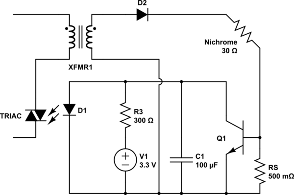
Or you can keep it simple and measure the current through the wire with a series resistor and capacitor that drives a simple transistor current-measuring circuit to turn-off the Triac photodiode. Something like this:

schematic

simulate this circuit – Schematic created using CircuitLab

You can also substitute D2 for an SCR and avoid dealing with the mains side completely. In that case the gate of the SCR can be directly driven like D1.

The only issue you have to be careful of, is that any regulation circuitry will be acting on average values of a non-sinusoidal waveform, so power calculations can introduce problematic non-linearities.

\$\endgroup\$
1
  • \$\begingroup\$ Thank you. But for now, I will try the other answer first as I don't have any opto-triac at hand. Will look into this again if that fails. \$\endgroup\$
    – John
    Commented Feb 2, 2019 at 7:32

Your Answer

By clicking “Post Your Answer”, you agree to our terms of service and acknowledge you have read our privacy policy.

Not the answer you're looking for? Browse other questions tagged or ask your own question.