1
\$\begingroup\$

I'm working on project that is Powered with 8 LiIon batteries/cells connected in parallel. Everything Works fine until batteries run out of "juice". For charging module I decided to use TP4056(@ 1A). Now, problem is - TP4056 module can charge only one LiIon cell at the time, so I need 8 modules for proper charging(one module per cell). There is two versions of TP4056 module, one with over discharge Protection(pins: B+, B-, OUT+, OUT-), one without Protection(pins: OUT+, OUT-), so I decided to go with module that has over discharge Protection(now I'm asking myself why I did that). Next is scheme(I don't have it but I'll write it):

  • Pins OUT+ and OUT- are connected in parallel(between modules). Those pins are in use as VCC for project(let's say it's "power source").
  • One cell is connected on B+ and B- pins of one module. With that way one module charges only one cell(as it should).

But! Yesterday I found that sometimes(since I buy from eBay) those Protection modules have problem/bug and they aren't reliable. Also later I found that cut-off voltage is 2.5V, while manufactuer recommends 3V(in most LiIon cells). I guess this design will fail so I decided to find another solution.

So my question is: How to make this same "design" with TP4056 without over discharge Protection(only OUT+ and OUT- pins)? How I should connect batteries with modules so only one module charges one cell? Any advices?

I paid more than €50 for those 8 cells and last thing I want to do is to destroy them with wrong charging "design".

I'm not sure is my solution correct so I wrote this question. My solution is:

  • Connect cell's positive pole to OUT+ pin of TP4056 and same thing with negativ pole(to OUT-).
  • Connect cells in parallel and that use as power souce.

So my thinking is: While charging, current will flow where is less resistance(as river in nature), it will flow from OUT+ through cell then from negative pole to OUT-. Is that correct? But if cells are used as power souce then current will flow as normal in parallel connection. Am I right?

Thanks a lot!

\$\endgroup\$
12
  • 1
    \$\begingroup\$ Series/Parallel Li-Ion arrangements, and Li-Ion charging in general are challenging. If you had gone ahead with individual chargers-per-battery, the batteries must be disconnected from each other to charge, the chargers will charge them to slightly different voltages, and when they are connected back in parallel there is a high probability of overcurrent/battery damage. Because your boards had protection, this likely would have caused it to "Work" by rapidly cycling the OC protection on and off randomly on all the cells ad the chargers attempted to balance the circuit. \$\endgroup\$
    – K H
    Commented Feb 4, 2019 at 18:48
  • 2
    \$\begingroup\$ The procedure to use cells in parallel is to start by selecting matched cells, charge them to "equal" voltage(you can only get so close) and then to balance them by connecting them in parallel with resistors for a period before spot welding them together to produce the final low impedance connection. Once this is done, it is crucial that you use suitable high cutoff and low cutoff voltages (you likely need a tighter range than you would for a single cell because there are limits to how much you can match your cells without buying thousands). \$\endgroup\$
    – K H
    Commented Feb 4, 2019 at 18:51
  • 1
    \$\begingroup\$ Having permanently paralleled the array, select a suitable charger/protection board(it may be advisable to use individual OC/fusing per cell) and charge the array together. Just one of your single cell chargers would be fine, although it would charge the bank much slower than necessary. \$\endgroup\$
    – K H
    Commented Feb 4, 2019 at 18:53
  • 1
    \$\begingroup\$ I often place something useful in the comments, but won't turn it into an answer unless I feel I can answer definitively/authoritatively/completely enough or if I'm not sure I'm providing what's needed. I'll ponder a bit longer and if someone else hasn't already answered and I feel I can fill in the remaining blanks I will tie it together in an answer. Your actual question is how you can produce a TP4056 design that bypasses part of the protection circuit, which is way above my skill level as it requires a bit of low end reverse engineering skill. \$\endgroup\$
    – K H
    Commented Feb 4, 2019 at 19:07
  • 2
    \$\begingroup\$ "8 LiIon batteries/cells connected in parallel" - this is where your project is fundamentally wrong. No one in normal engineering will connect 8 cells in parallel, it is not possible to match all 8 to 1-2% along the entire charge-discharge curve (and their protection circutry), even when sorting cells in factory quantities. See electronics.stackexchange.com/a/386699/117785 \$\endgroup\$ Commented Feb 4, 2019 at 19:19

2 Answers 2

5
\$\begingroup\$

Once you have a number of cells permanently connected in parallel you can treat them as a single cell with larger capacity for both discharge and charge. Separating the cells to charge them is overly complex.

Design a single Lion charger and BMS (individual cell temp will show faults) that charges your total battery capacity at its best possible rate.

There will be small differences in the cells and the charging (and discharging) current will not be exactly equal across the cells, but the terminal voltage of all cells will be absolutely identical (they are shorted together after all). The worst case problem you have is that one cell may fail open circuit forcing the other cells to a higher charge current and potentially resulting in a cascade failure of your pack. If temperature warning is not in your judgement fast enough to provide failure detection, then you could put a Hall Effect current sensor in each battery connection.

Based on your comment:

Batteries are in holders(it is cheaper than welding them together). Batteries are in housing and charging one by one cell(outside housing) is not in my interest(since they are below two PCBs)

You should definitely NOT do this. Taking the batteries out of the holder/housing and charging them separately using TP4056 chargers will NOT provide matched terminal voltages from your multiple chargers. You will introduce uncontrolled balancing currents when you plug them back into the holder/housing. The balancing current will certainly not destroy the batteries, but depending on each cells temperature and terminal voltage the circulating currents could be several hundred mA up to several amps.

Putting series fuses in for each cell (as suggested in the comments) is a viable way to protect against a short in one cell (a single cell fire as opposed to an 8 cell fire ...perhaps). You could certainly consider that.

The TP4056 can't be paralleled easily because the terminal voltage and current thresholds will be different for every charger chip. You might however be able to get away with this in a limited form since the TP4056 is a CC/CV linear charger. I would not suggest you use more than 3 of the simple variety in parallel.

The 168650 cells vary a lot, here's a typical datasheet.

I would be concerned that if you ever had a fault where only one battery cell is in place, you are seriously overcharging at 3A particularly with no temp sensing in place. However if you are comfortable that your paralleling wiring and connections for the pack are safe enough, then 3A may be a viable charge current for the pack.

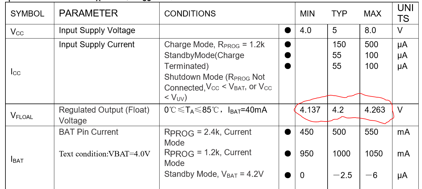
The datasheet for the TP4056 shows that there is a range of output voltages for the CV mode. If your battery pack is depleted to say 3.4V then you can be sure that all three chargers would be in CC mode, so far so good. However they will switch from CC to trickle and CV at different times (voltages), with the highest voltage chip defining the final switch point.

enter image description here

Three chargers would produce 3A, then 2A + 1 Trickle, then 1A + 2 trickle, then 3 trickle as the terminal voltage of the pack rises. Eventually all three chargers would terminate, with the highest voltage chip defining that point.

\$\endgroup\$
10
  • \$\begingroup\$ So I can connect cells in parallel and 8 TP4056s in parallel with batteries? Those "safety features" are overkill for this project(in my opinion). Why? Whole project will suck 0.5A at maximum load, that is .06A per cell. Cells are new and they can handle more than 1A of charging current. So I guess there is less than 1% chance for failure. I just want to charge cells without damage. \$\endgroup\$
    – Pararera
    Commented Feb 4, 2019 at 19:31
  • \$\begingroup\$ If your charging current is only 1A, then you only need 1 * TP4056. If you need charging current to be over this 1A limitation then you need to select a different charger. You cannot connect multiple TP4056's in parallel. \$\endgroup\$ Commented Feb 4, 2019 at 19:42
  • \$\begingroup\$ Only problem is that I can't find another module than TP4056 for parallel cells. Maybe I'll try bypass Protection circuit. It's more and more complex :| \$\endgroup\$
    – Pararera
    Commented Feb 4, 2019 at 19:45
  • \$\begingroup\$ Thanks for edit. I'll first try with TP4056 with protection. Maybe protection on every module works fine. If not, I'll guess what to next. Thanks a lot! \$\endgroup\$
    – Pararera
    Commented Feb 5, 2019 at 5:20
  • 1
    \$\begingroup\$ The whole premise of my answer was that you would have the cells bonded together, so treated as a single cell. One connected together (even if you have fuses to each cell, they would never be separated. \$\endgroup\$ Commented Feb 5, 2019 at 14:46
0
\$\begingroup\$

You may use multiple BMS chips OR replicate what is inside with lower RdsOn FETs and added circuits to amplify current sense of each using Quad Op Amps and ground side detection.

Then limit by the highest input Isense on each during CC mode using Diode Or or in software with MUX in to regulate Vgs .

Then compute or measure the smallest input at 10% cuttoff using inverted Current sense with offset per bat to “diode or” comparator in CV mode for cutoff threshold.

If you have a MUx and ADC to uC then this can be done in software and register the cell # with the weakest capacity or ESR by detection of source used to regulate CC or cutoff. These will most likely be the ones to replace or pair with other battery arrays if more than 1% difference.

Yet this BMS method will extend the life of the pack albeit the strongest cells will only have the charge accepted by the weakest cell in parallel.

For optimizing capacity of all cells and preventing over charge rate in CC or over time in CV mode when fully charged, this requires separate switches or active switch mode charge pumps turned on sequentially so that you can reduce current by P WM the average current flow during CC transition to CV then the transition to cutoff independently for each cell, with a common programable (by jumper or software) CC rate and CV terminal voltage.

Temp sensing is useful in case one cell has developed Dendrite shorts which raise the cell temp above normal levels during anytime.

\$\endgroup\$
2
  • \$\begingroup\$ I guess I'll quit from this project since there's no simple(for me) solution for charging design. I need big capacity and don't need "super-pro-complicated" charging circuit. \$\endgroup\$
    – Pararera
    Commented Feb 5, 2019 at 17:28
  • 1
    \$\begingroup\$ Expensive to buy or buy cheap to make if someone designs. The benefit is longer battery life if you learn how to control this from Battery University site parameters. \$\endgroup\$
    – D.A.S.
    Commented Feb 5, 2019 at 17:29

Your Answer

By clicking “Post Your Answer”, you agree to our terms of service and acknowledge you have read our privacy policy.

Not the answer you're looking for? Browse other questions tagged or ask your own question.