3
\$\begingroup\$

I am working on a dimming circuit to be operated by an ESP8266.

I have read a lot on this over internet and got a working circuit as well. But myself I am not satisfied with my understanding of TRIACs.

This question is not related to the dimmer directly, but more related to the operation of the TRIAC. I am not holding any electronics degree from any university, rather its my hobby and I am a self taught guy (thanks to internet).

The circuit is really simple. I am detecting zero-cross with the help of 4N35 and driving the TRIAC through MOC3012 using a GPIO of ESP.

enter image description here

Now today I got some free time and I was reading more about TRIACs and specially the datasheet of BTA16.

Here is the datasheet from farnell:

http://www.farnell.com/datasheets/1699992.pdf

Now as I am operating AC load (can be resistive or inductive load. Eg. operating bulb or fan) using the TRIAC.

The MT2 is connected to gate through a current limiting resistance and isolation side of MOC.

So the first question is, am I ever operating the triac in IV quadrant?

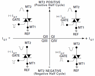
What I undrestand is, when the gate is positive and M2 is negative with respect to MT1, the triac is operating in quadrant IV.

Now as my gate is connected to MT2, and when MT2 is negative (compared to MT1), my gate is also negative. So I am never in the IV quadrant.

Please correct me if I am understanding something terribly wrong.

Now I am asking this question as the snubberless part (I want to use because of possible inductive load) of BTA series (BTA-600BW) does not operate in quadrant IV. I am saying this as I don't see any gate current specification for quadrant IV for the snubberless part (in the datasheet).

Also, in some reference circuits, I see people specified connect MT2 to HOT (phase) and other point of load to COLD (neutral).

I don't understand why does this matter for AC current. Please explain if that really has got a meaning.

Can someone please let me know, if I have learnt things in the correct way?

\$\endgroup\$
0

1 Answer 1

1
\$\begingroup\$

So the first question is, am I ever operating the triac in IV quadrant?

No, this is never operating in quadrant IV.

What I understand is, when the gate is positive and M2 is negative with respect to MT1, the TRIAC is operating in quadrant IV. Now as my gate is connected to MT2, and when MT2 is negative (compared to MT1), my gate is also negative. So I am never in the IV quadrant.

This is correct. Because the gate current (through opto-TRIAC U5 and resistor R16) comes from MT2, the gate will always be the same polarity as MT2.

TRIAC Quadrants

From this diagram, it should be visible that with the gate power coming from MT2, it will only ever match quadrants I and III, which is a typical application for the TRIAC.

You are correct to avoid quadrant IV, especially for "snubberless" devices. I have a simulation of such "snubberless" quadrant IV operation here. That simulation shows that quadrant IV operation "works" but don't believe the simulation! The simulator lies; "snubberless" TRIACs won't fire from quadrant IV, or very poorly. In general, just avoid quadrant IV altogether. That was just a conceptual test of the simulator.

Gate Resistor

About the value of R16: this should be calculated to limit the gate current, as this varies for different TRIACs. For many devices, this is going to be 100-330Ω (for 120 VAC) or 330-680Ω (for 240 VAC).

The gate resistor is calculated like this:

\$R_{min} = V_{in(pk)}/I_{GM}\$

Where Vin(pk) is the peak of the AC waveform - usually 170 V or 340 V for 120 VAC and 240 VAC respectfully, and Igm is the max gate current from the datasheet.

For the BTA16 device, Igm is (a whopping) 4A, so if operating at 120 VAC, the gate resistor can be a minimum of 170/4 = 42.5Ω which means each pulse "on" could inject max 4 A into the gate. Also consider the power through this resistor during a pulse; 4*170-Vf is a lot of watts. Granted, the duty cycle is very low, but there will be heating and it will not be negligible.

Then this current is also going through U5, a MOC3012M - the MOC301x are rated to block a max of 250 V peak - this may be too low for 240 VAC operation. (Must check all datasheets.) The TRIAC inside this has a \$I_{TSM}\$ (peak current) rating of 1.0 A max. So the above resistor must be re-sized for this (170/1) = 170Ω minimum.

Perhaps even more important, consider specifying a pulse-rated resistor for the gate - you will find that using any-old resistor (such as a carbon, metal-film, or especially power wire-wound) will fail open over time.


Also, in some reference circuits, I see people specified connect MT2 to HOT (phase) and other point of load to COLD (neutral). I don't understand why does this matter for AC current. Please explain if that really has got a meaning.

In theory, it should not matter if MT2 is tied to HOT (load on MT1), or if MT1 is tied to HOT (load is on MT2.) However, consider the gate pulse in these two scenarios:

  1. MT2 tied to HOT, load on MT1: gate pulse comes from HOT, so is always well-defined.
  2. MT1 tied to HOT, load on MT2: gate pulse comes from MT2 (the load), which may impose resistance / capacitance / inductance.

For this reason, it should be wired exactly like your schematic, with the load on MT1.

An added benefit to this is, if MT2 is the HOT terminal, then the whole load circuit will be near zero volts when the TRIAC is off. From a functional standpoint this is moot, but it is a little safer when accidentally touching the load during prototyping.

\$\endgroup\$

Your Answer

By clicking “Post Your Answer”, you agree to our terms of service and acknowledge you have read our privacy policy.

Not the answer you're looking for? Browse other questions tagged or ask your own question.