I'm new to electronics, and I'm trying to use a boost converter to get 5V at 1.2A from a lithium ion battery. I've selected the TPS61232 step up converter for this solution.
The datasheet has a recommended layout:
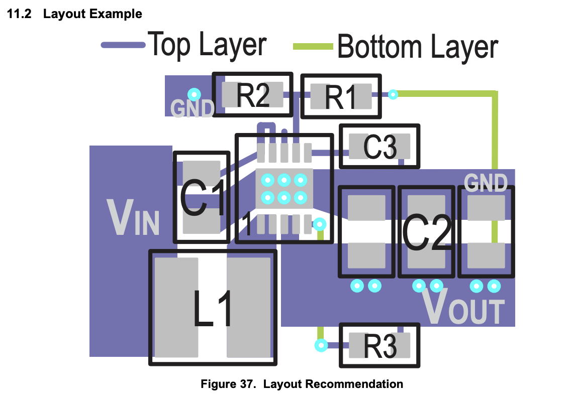
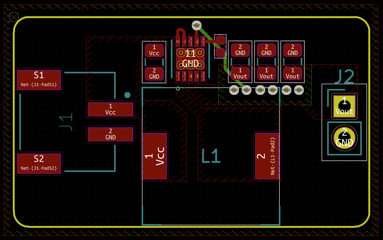
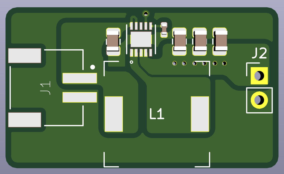
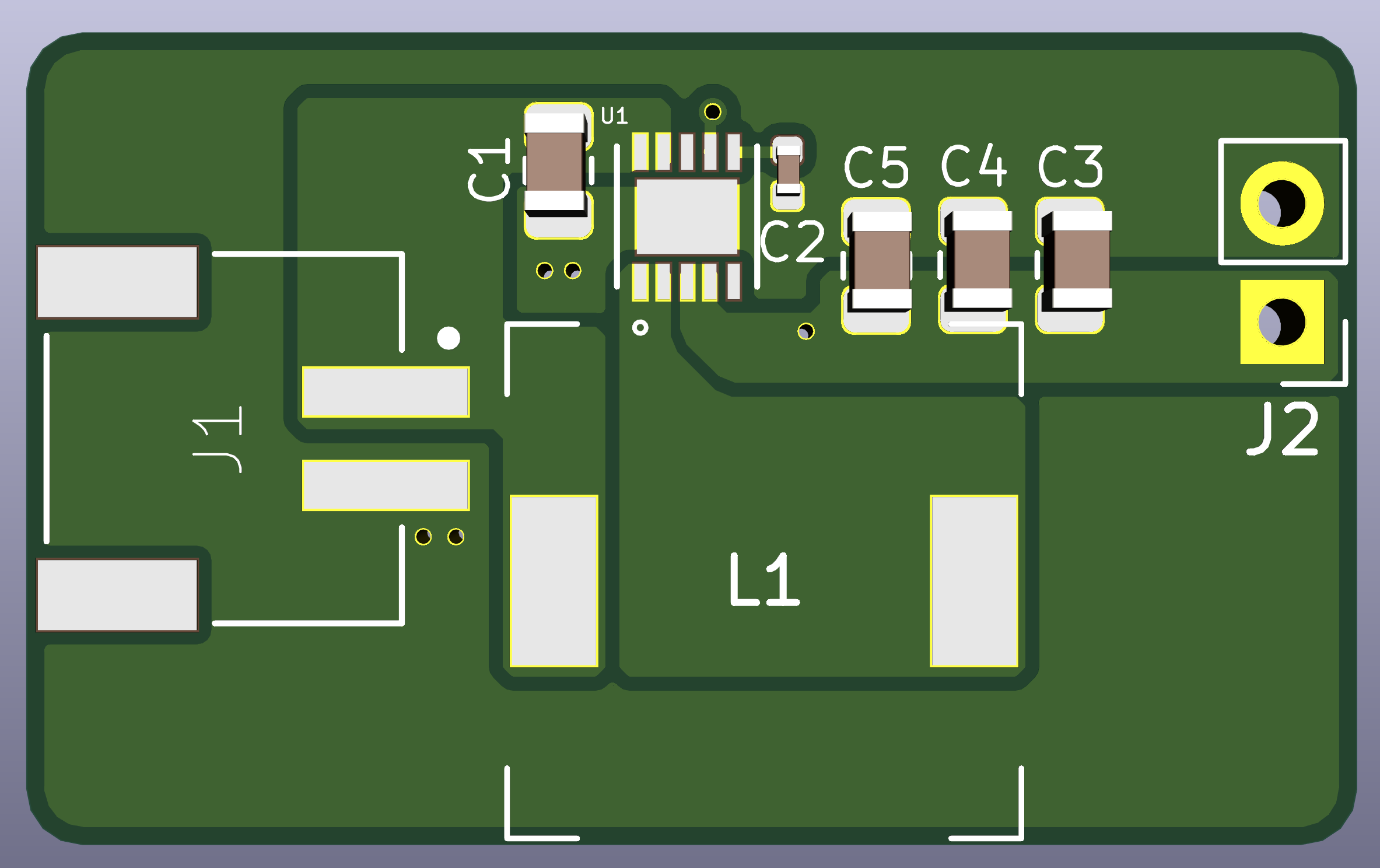
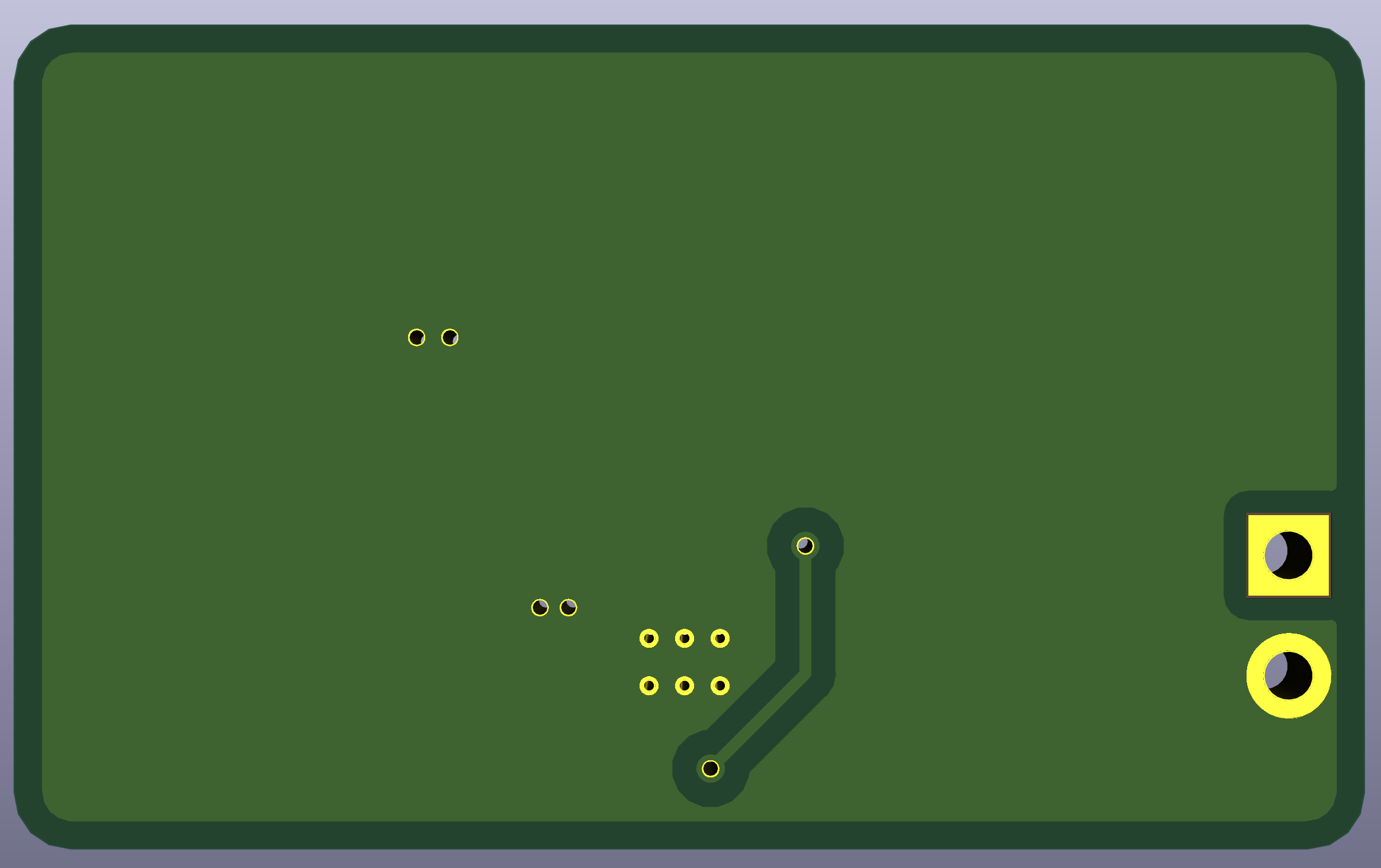
It's all well and good unless you have a giant inductor (which I have). I tried to capture the concepts of the example layout, but I don't know if I'm missing anything fundamental. Does this look like a rational layout?
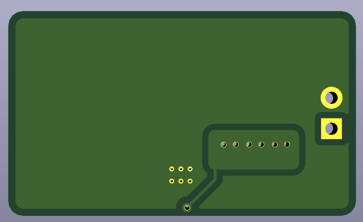
I added the vias under the IC which I think are probably dual purpose: heat dissipation and potentially also to wick out some solder so the IC doesn't sit on a solder bubble.
I used a lot of pours which I assumed were to provide additional surface area to dissipate heat.
Finally, I added the vias on the Vout pour, but I'm not sure what those vias are for really.
Additional Details
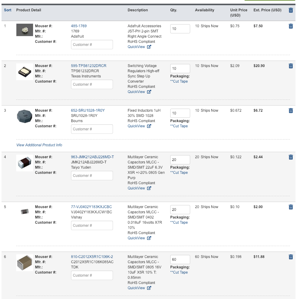
Here is my current planned BOM:
Inductor Options
Here are some inductors I think I could use and give myself some more space:
- This one seems better in about every way. Lower tolerance, higher DC current, lower DCR, higher SRF (this is good, right?), etc. It's just way more expensive. https://www.mouser.com/ProductDetail/Wurth-Electronics/744316100?qs=sGAEpiMZZMsg%252by3WlYCkUy4%252bqPuxOV5JxsS7NSlX2UA%3d
- My IC has a 2 MHz switching frequency so I feel like I could stand to have a lower SRF. Is that true? Like maybe this one at 50 MHz? https://www.mouser.com/ProductDetail/Bourns/SRP6050CA-1R0M?qs=sGAEpiMZZMsg%252by3WlYCkUwWVs%252bZAfRN3be00zVNyvZQ%3d
- I'm looking to provide 1.2A (my actual output current is quite a bit less really, but I'm looking at 1.2A for the sake of the exercise) at 5V supplying a minimum of 2.8V (from a nearly dead Lithium Ion battery). It looks like my efficiency is going to be somewhere near about 80%. If I call it 70%, then I think it calculates like this . . . my output power is 5V * 1.2A = 6W. With a 70% efficiency I need 8.6W from the supply at 2.8V. So, 8.6W / 2.8V = 3.1A? Well, nevermind . . . after all of that, I don't see any smaller inductors with a lower current rating so it's moot. Still, am I making sense on any of these assumptions?
Implemented changes
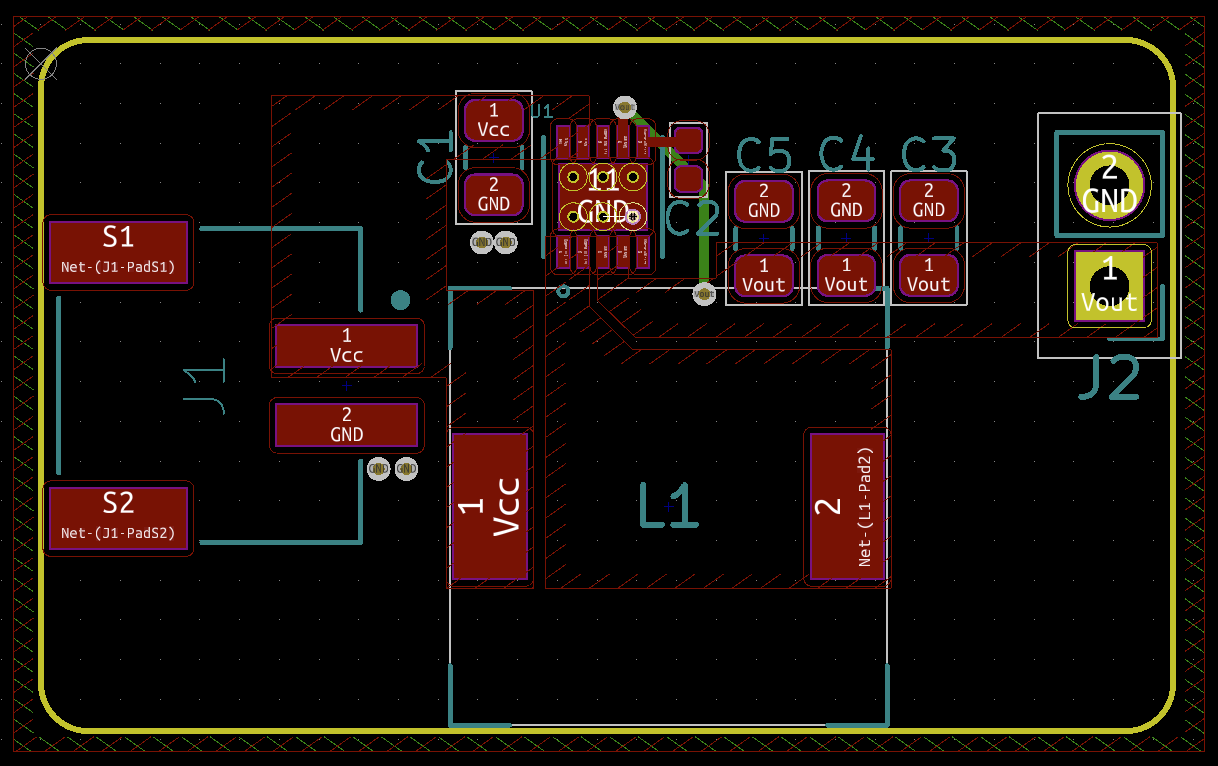
Here's what I've done based on (my understanding of) current answers:
- I changed all of the pours (and moved caps) to try to keep pours as straight as possible to avoid bottlenecks.
- I flipped the J2 jumpers around so that the Vout and GND pins will be as close to the output caps as possible. I think that's to reduce the inductance as the current traveled through vias to the other side of the board to get to the ground pin?
- I extended the top side of the board and used .6mm vias with .3mm drill holes to connect Vout to pin 7 so that the ground pour will wrap all the way around the top of the board and provide more direct routes for current to flow to various components.
- I added vias near the ground pin so current to the ground pad can get to the pin more directly (I made this one up myself . . . it might be a bad idea).
- I gave the top ground pour 3mm clearance to increase the surface area slightly.
- I put the ref symbols back because it was dumb to hide them in the first place.

