7
\$\begingroup\$

I have met with a scalar control algorithm for a permanent magnet synchronous motor. I haven´t heard about it before so I decided to develop a dynamic model to further analyze this control algorithm. Unfortunatelly I haven´t got the Matlab with the SimPowerSystems library so I decided to create this model in Scilab.

I have been using below given equations for PMSM simulation:

\$\frac{\mathrm{d}i_d}{\mathrm{d}t} = \frac{1}{L_d}\cdot(u_d-R\cdot i_q+L_q\cdot\omega_e\cdot i_q), \\ \frac{\mathrm{d}i_q}{\mathrm{d}t} = \frac{1}{L_q}\cdot(u_q-R\cdot i_q-L_d\cdot\omega_e\cdot i_d - \omega_e\cdot\psi_m), \\ \frac{\mathrm{d}\omega_m}{\mathrm{d}t} = \frac{1}{J}\cdot(1.5\cdot p\cdot\psi_m\cdot i_q - T_l),\\ \omega_e = p\cdot\omega_m\$

where \$p\$ is number of pole pairs

The parameters of the model:

\$L_d = 1.365\cdot10^{-3}\,H \\ L_q = 1.365\cdot10^{-3}\,H \\ R = 0.416\,\Omega \\ \psi_m = 0.166\,Wb \\ p = 2 \\ J = 3.4\cdot10^{-4}\,kg\cdot m^2 \\ kF= \frac{3.2}{(2\cdot\pi\cdot\frac{1200}{60})^2}\,\frac{N\cdot m}{(rad\cdot s^{-1})^2}\$

Here is my overall simulation model enter image description here

The motor is loaded by below given torque

\$T_l = kF\cdot\omega^2\$ which is removed in step wise manner at \$t=0.4\,s\$

The U/f block enter image description here

The PMSM Model block enter image description here

The Inverse Park Transform block enter image description here

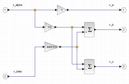
The Inverse Clarke Transform block enter image description here

Ther results are following

Stator currents enter image description here

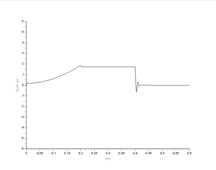
Motor torque enter image description here

Reference and actual mechanical speed enter image description here

Stator voltage in q axis enter image description here

I have doubts about correctness of my model due to the fact that the actual motor speed differs from the reference speed. I expected that they will equal because of the modeled machine is a synchronous motor. Does anybody know where I did a mistake? Thanks in advance for any suggestions.

\$\endgroup\$
10
  • \$\begingroup\$ Have you tried with the power invariant Clarke transform? \$\endgroup\$ Commented Feb 12, 2019 at 7:59
  • \$\begingroup\$ @a concerned citizen Thank you for your reaction. Do you mean changing the gains in the Inverse Clarke Transform block? \$\endgroup\$
    – Steve
    Commented Feb 12, 2019 at 21:02
  • \$\begingroup\$ Yes, but now I realize the matrix is only for displaying the currents. Maybe there are similar scaling coefficients that need to be added when using the dq equations? \$\endgroup\$ Commented Feb 13, 2019 at 7:39
  • \$\begingroup\$ As far as I know the Park transformation only realizes rotation of coordinate system via multiplying by \$e^{j\phi}\$ and does not change module of the space vector. \$\endgroup\$
    – Steve
    Commented Feb 13, 2019 at 10:42
  • \$\begingroup\$ Yes, but you don't only apply the Park transform to get to the dq-reference frame. That is, it's not a simple matter of multiplying with a sin/cos and adding/subtracting in a 3phase to a 2phase, the Clarke matrix, or, at least, the coefficients are also there. That \$e^{j\phi}\$ has meaning in an orthogonal system, not a 3phase, so you first apply 3->2 and then sin/cos, unless you complicate with doing it directly, but even then you have scaling coefficients. That's what I referred to when I mentioned the scaling coefficients. But I am also not sure, that's why I'm stuck with comments. \$\endgroup\$ Commented Feb 13, 2019 at 13:24

1 Answer 1

0
\$\begingroup\$

The Inverse Clarke Transform block: x_c is -(x_a + x_b)

\$\endgroup\$
1
  • 5
    \$\begingroup\$ Can you expand this answer? \$\endgroup\$
    – Voltage Spike
    Commented Jul 18, 2022 at 4:48

Your Answer

By clicking “Post Your Answer”, you agree to our terms of service and acknowledge you have read our privacy policy.

Not the answer you're looking for? Browse other questions tagged or ask your own question.