1
\$\begingroup\$

I am looking at the datasheet for the MCP4725 DAC and trying to find the minimum voltage the DAC will output. In other words, when my code tells the DAC to output 0v, what will the output be? There are two parameters listed in the datasheet that I think are related to what I am looking for. One is the Offset Error of the DAC, and the other is the Output Low Voltage. Anyone know which one is the parameter that tells me the minimum DAC output?

Here is the MCP4725's datasheet: http://ww1.microchip.com/downloads/en/DeviceDoc/22039d.pdf

\$\endgroup\$
2
  • \$\begingroup\$ Ok. So i guess I should use a differential or summing amplifier to remove that output low voltage to get a true 0v output. I am not so worried about output precision. \$\endgroup\$
    – Saunders
    Commented Feb 22, 2019 at 21:19
  • \$\begingroup\$ I take it back. I misread. Check my answer. \$\endgroup\$
    – DKNguyen
    Commented Feb 22, 2019 at 21:23

2 Answers 2

1
\$\begingroup\$

Output low voltage refers to the digital interface and is not relevant to the DAC output.

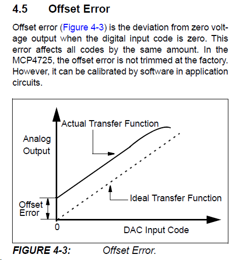
The offset error is the output voltage with code = 000 and will be greater than 0V since it's a single supply DAC (and output load is specified as a 5K resistor to ground).

Worst case is specified as 0.75% of Vdd and typical is 0.02% of Vdd (over 2.7 to 5.5V Vdd).

So with a 5V supply, typical should be 1mV and worst case 37.5mV. The typical curve Fig 2.8 shows typical about 1.6mV for a 5.5V supply and a bit over 1mV for a 2.7V supply.

But you should not count on the output getting closer than some tens of mV of either supply (depending on loading, unit-to-unit variations, temperature, supply voltage etc.).

\$\endgroup\$
2
\$\begingroup\$

The "Output Low Voltage" is listed under the "Digital Interface" section of the datasheet. It is the maximum allowable output voltage when the I2C interface is trying to send a logical zero. It is unrelated to the DAC analog output. Therefore, the "Offset Error" is your minimum output voltage. It also biases every other DAC output level as well.

Check section 4.5 of the datasheet:

Microchip MCP4725 Datasheet

From Microchip MCP4725 Datasheet

\$\endgroup\$
3
  • \$\begingroup\$ Interestingly, Microchip does not put a '\$\pm\$' in front of their offset error. This implies to me that it is either always positive, or that Microchip missed dotting an 'i'. Unfortunately, there's no way to tell -- and if you really need to go down to zero, you need to add in the offset yourself anyway, for those parts that are offset up. \$\endgroup\$
    – TimWescott
    Commented Feb 22, 2019 at 22:35
  • \$\begingroup\$ That is interesting. It's almost like they just tested it at zero on a unipolar supply for output code 000 and didn't bother to test for any other code where a negative offset would actually be visible . Actually, that's exactly what's implied from the Conditions column for that spec. \$\endgroup\$
    – DKNguyen
    Commented Feb 22, 2019 at 22:45
  • \$\begingroup\$ I could conceive of them having designed it so that it never hits 0V -- there's certainly a whole lot of DAC applications where you would never want that, and pulling things down to the negative rail would make for ugly nonlinearity errors right at the end of the range. I don't know this, mind you -- I'm just guessing. Or bloviating. Or something. \$\endgroup\$
    – TimWescott
    Commented Feb 23, 2019 at 0:47

Your Answer

By clicking “Post Your Answer”, you agree to our terms of service and acknowledge you have read our privacy policy.

Not the answer you're looking for? Browse other questions tagged or ask your own question.