1
\$\begingroup\$

I have a signal (digital) which has output levels of 0V (logic 0) and 3.5V (logic 1).

I would like to know if it is possible to shift it between -2V (logic 0) and 1.5V (logic 1).

I found here on stackexchange and on google various example, but they all assume positive levels (0-5 or 0-3.3) and I don't really understand how to make them work in my case.

Thanks for all the help

EDIT after a couple of questions:

  • I have available easily on board: -2V, 0V, 1.5V, 5V
  • I am sending the signal to a CMOS logic gate

EDIT 2: Just to add a bit more to my question:

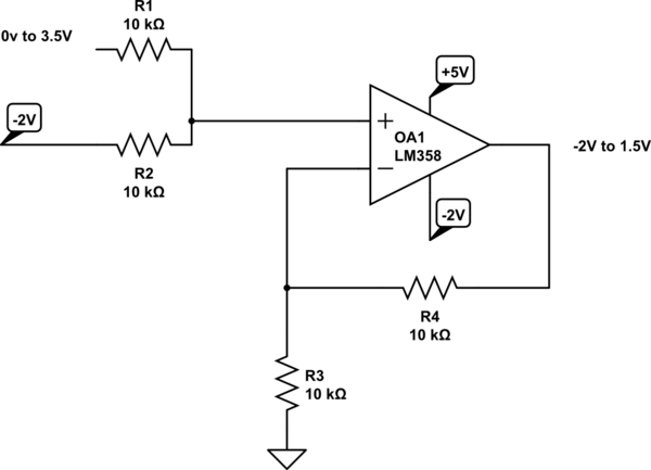
if you look at this thread Level shifting a +/- 2.5V signal to 0 - 5V

the first answer provides a very nice circuit to do level shifting.

My problem is that I do not understand how to modify the circuit to fit my needs (see above).

In particular, I am quite puzzled by the supply value of the OpAmp. It looks to me I should use +1.5 and -2, but then I get lost in understanding what is going on.

\$\endgroup\$
4
  • \$\begingroup\$ Sure it's possible - what power supplies do you have available and what are you interfacing to? \$\endgroup\$
    – Andy aka
    Commented Mar 8, 2019 at 10:22
  • \$\begingroup\$ 3.5 is a bit strange. But anyway the simplest way is to use digital isolation and power supplies according to your needs. \$\endgroup\$
    – user76844
    Commented Mar 8, 2019 at 10:24
  • \$\begingroup\$ Edited with clarification, thanks! \$\endgroup\$
    – Cesco
    Commented Mar 8, 2019 at 10:48
  • \$\begingroup\$ What’s the speed & edge slew rate required for the signal? \$\endgroup\$ Commented Mar 8, 2019 at 15:54

2 Answers 2

1
\$\begingroup\$

schematic

simulate this circuit – Schematic created using CircuitLab

The LM358, being a single supply op amp, saturates in the negative direction within a few mVs of the negative supply rail.

\$\endgroup\$
0
\$\begingroup\$

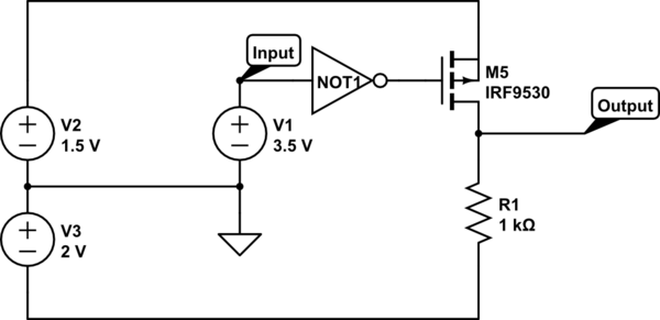
You did not mention any more specific requirements for the output signal, i.e. frequency and output impedance, but this is a very simple circuit that could get the job done for low to medium frequencies and with an output impedance determined by R1:

schematic

simulate this circuit – Schematic created using CircuitLab

V1-V3 represent your power supplies of +3.5V, +1.5V and -2V w.r.t. GND.

Using a P-channel MOSFET you can switch the +1.5V line to the output. The pull down resistor R1 provides -2V to the output when the MOSFET is off.

Because we need a P-MOSFET here, which turns on when the gate is driven low, an additional inverter is needed. This inverter however can be as simple as another MOSFET and a resistor.

Note that I just picked a random FET to illustrate the circuit. You would need one that already turns on sufficiently at -3.5V.

\$\endgroup\$

Your Answer

By clicking “Post Your Answer”, you agree to our terms of service and acknowledge you have read our privacy policy.

Not the answer you're looking for? Browse other questions tagged or ask your own question.