3
\$\begingroup\$

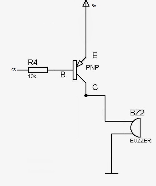
I have connected a 3906 PNP transistor base to a GPIO pin of ESP32 board. Emitter is connected to 5v and collector is connected to a buzzer. When I program the buzzer (send a HIGH from ESP32), it is permanently on. When I check it against a multimeter, the transistor turns on even when base current is 3.4v (when I though it turns on only if voltage is less than 0.7v).

To cross check the transistor and buzzer, I directly connect base to 5v and the transistor is turned off. Connecting to ground turns on. So, it works correctly when connected directly.

For those who would like to suggest a NPN transistor, I have tried using 3904 NPN transistor and everything works as expected. However the issue is that when programming, all the pins of ESP32 are high by default and the buzzer is ON until programming done.

Can someone tell me how to solve this issue? I need to use PNP transistor only. Thanks in advance.PNP circuit
\$\endgroup\$
5
  • 2
    \$\begingroup\$ Your words regarding the collector and emitter connections do not agree with your schematic. Can you make them consistent somehow? What do you mean by "program" the buzzer? When you measure the voltage at the base, where exactly are the two points where you are making the measurement? \$\endgroup\$ Commented Mar 10, 2019 at 12:51
  • 1
    \$\begingroup\$ Your PNP is "looking" at its base-emitter voltage - that's the only thing it "knows" about. It doesn't "know" or "care" what its base voltage is with respect to some arbitrary point you call ground. \$\endgroup\$
    – brhans
    Commented Mar 10, 2019 at 13:42
  • \$\begingroup\$ Yes. I get it now after a comment from @Elliot Alderson. Will recheck it based on his comments using a pull-up resistor. \$\endgroup\$
    – Praveen
    Commented Mar 10, 2019 at 14:07
  • \$\begingroup\$ How much current does the buzzer require when operating? And, when you say "only PNP" do you mean "only 1 PNP?" Or can it be two? \$\endgroup\$
    – jonk
    Commented Mar 10, 2019 at 17:20
  • \$\begingroup\$ If you could use a piezo disk and drive it directly by putting a high frequency waveform on the GPIO, things would be a lot simpler. \$\endgroup\$ Commented Mar 10, 2019 at 17:52

5 Answers 5

4
\$\begingroup\$

I suspect you are trying to drive the PNP base with a 3.3V logic signal while controlling 5V to the buzzer. That just isn't going to work. To turn the transistor off (non-conducting) you need to raise the voltage on the base to be close to the emitter voltage, or about 5V. You can't do that with a 3.3V logic signal. You make a PNP transistor conduct by lowering the base voltage about 0.7V below the emitter voltage, not by setting the base voltage to 0.7V above ground.

You might be able to add a pullup resistor from the base itself to 5V to turn the transistor off when the logic output is 3.3V. Select resistor values so that when the 3.3V signal is low the voltage at the base is less than 4.3V. You would also have to select resistor values that limit the current that will flow back into the 3.3V logic output when that output signal is high. This is all just speculation, you haven't provided a datasheet for the device that is driving the base.

\$\endgroup\$
2
  • \$\begingroup\$ Yes. Correct. I am trying to drive a PNP base with a 3.3v signal and 5v to the buzzer. I was under an assumption that its 0.7v above ground. Thanks for clearing it out. Will add a pull up and let know if it works. Regarding the resistor values, I will do a trial and error and check the approx. value. \$\endgroup\$
    – Praveen
    Commented Mar 10, 2019 at 14:04
  • 2
    \$\begingroup\$ View the bipolar transistor's base-emitter as a DIODE. To turn OFF that diode, the voltage needs to be near zero volts(0.2, 0.1) or even moderately reverse-polarity. To reverse-bias a 2N3906 base-emitter, the base voltage needs to be above the emitter voltage \$\endgroup\$ Commented Mar 10, 2019 at 14:08
1
\$\begingroup\$

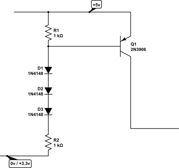
try this

schematic

simulate this circuit – Schematic created using CircuitLab

\$\endgroup\$
5
  • \$\begingroup\$ what are the three diodes for, may I ask? Is is to reduce voltage by 2.1? \$\endgroup\$
    – Praveen
    Commented Mar 10, 2019 at 14:14
  • \$\begingroup\$ Why bother with the diodes (at least so many of them) when the resistors can be selected to provide the right voltage? \$\endgroup\$ Commented Mar 10, 2019 at 14:16
  • \$\begingroup\$ Rail bounce of either +3.3 or +5 will allow intermittent triggering of the transistor. \$\endgroup\$ Commented Mar 10, 2019 at 14:21
  • \$\begingroup\$ Anyone has a circuit with only resistors? I have added a pot to base as a pull-up to get right resistor value. But it does not seem to work. \$\endgroup\$
    – Praveen
    Commented Mar 10, 2019 at 14:23
  • \$\begingroup\$ If you don't specify the buzzer's current, then the transistor can only be driven iinto saturation. Try a 1Kohm pot, in series with 100 ohm resistor to ensure base current will not exceed (5v - 0.7v) / 100ohm = 43mA. That scaled by 10X to ensure saturation of the 2N3906, allows 430mA (0.43 amp) thru the buzzer. If the buzzer is a relay-type, you need a 0.1uF across the buzzer to absorb inductive spikes, otherwise the 2N3906 will be destroyed. And, attach the 2N3906 base to wiper of the pot. \$\endgroup\$ Commented Mar 10, 2019 at 21:21
1
\$\begingroup\$

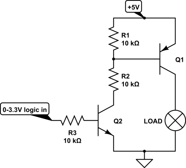
The classic way to do this is with a circuit like this:

schematic

simulate this circuit – Schematic created using CircuitLab

Here, any input signal above ~0.7V switches the NPN transistor Q2 on, which pulls current through Q1's base to ground. When Q2 off, R1 pulls the base high, to keep the PNP transistor off. R2 and R3 are here to limit current through the bases of the transistors.

\$\endgroup\$
5
  • \$\begingroup\$ Thanks for this circuit. When searching, I found this link electronics.stackexchange.com/questions/245976/… which has a similar circuit. I am looking for any solution with only resistors. If that does not work, I will go this way. Thanks for the circuit. \$\endgroup\$
    – Praveen
    Commented Mar 10, 2019 at 14:50
  • \$\begingroup\$ I'm sure a resistor-only solution is possible, but it probably wouldn't be reliable and I wouldn't want to use it in anything I design. The NPN transistor here doesn't need to be able to handle any significant amount of power, so you can use a cheap MMBT3904 or something for it, even if the PNP transistor is switching a lot of current (do the analysis for your specific application though!) \$\endgroup\$
    – Hearth
    Commented Mar 10, 2019 at 14:54
  • 2
    \$\begingroup\$ I tried your solution, but the issue still stays. I can as well use only a single NPN transistor for this. The issue is that ESP32 pins are high by default while programming which turns on the buzzer while programming. Now, the same issue repeats. Is there a similar circuit with PNP on the left and NPN on the right ? \$\endgroup\$
    – Praveen
    Commented Mar 10, 2019 at 15:08
  • 1
    \$\begingroup\$ @Praveen If your only problem is that the buzzer turns on when the thing is programming, the easiest thing to do is to just claim it's a feature: "Buzzer sounds to let you know it's being programmed!" More seriously though, just go with analogsystemsrf's answer if that's what you want. \$\endgroup\$
    – Hearth
    Commented Mar 10, 2019 at 15:16
  • \$\begingroup\$ and analogsystemsrf, I did read the comment. I did not understand what is Rail bounce. Rather than feeling dumb, I was checking other options. If someone can suggest what is rail bounce method, I would be glad. \$\endgroup\$
    – Praveen
    Commented Mar 10, 2019 at 15:52
1
\$\begingroup\$

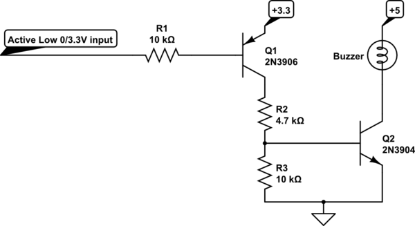
This will work:

schematic

simulate this circuit – Schematic created using CircuitLab

The emitter of Q1 is at 3.3V so it is off when the input is floating or at 3.3V. When the input goes low, Q1 turns on, providing almost 3.3V at the top end of R2, providing about 0.5mA to the base of Q2. R3 drains away any leakage Q1 has when it is off.

If the buzzer takes more than about 5-10mA then decrease R2.

\$\endgroup\$
1
\$\begingroup\$

schematic

simulate this circuit – Schematic created using CircuitLab

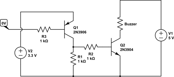
You may have to play with resistor values.

\$\endgroup\$

Your Answer

By clicking “Post Your Answer”, you agree to our terms of service and acknowledge you have read our privacy policy.

Not the answer you're looking for? Browse other questions tagged or ask your own question.