6
\$\begingroup\$

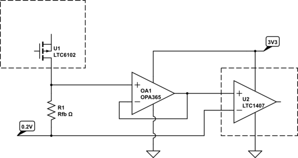
I'm thinking about current sensing with a high dynamic range (10 mA - 20 A) and using LTC6102 as a high-side current sense amp (the voltage would be 54.6 V max, a 13S6P Li-ion battery).

The ADC I'm planning to use is LTC1407 (12-bit 1.5 MS/s).

I am planning to use OPA2365 as a unity-gain buffer between the current-sense amplifier and the ADC.

The current-sense amplifier provides an output current proportional to the sense voltage and given the high voltage and small package size, the output current has to be 1 mA full scale which requires a rather high value output resistor and thus a buffer is needed between the current-sense amplifier and the ADC.

The op-amp requires a small (-0.1 V) negative supply for the output to go down to 0 and it's important to go down to 0 in my case because of the high dynamic range I want.

I could try and do a negative supply e.g. a crude one with an additional battery between ground and the negative supply of the op-amp, but I would rather avoid it to simplify the circuit.

Is there a way that I can measure down to 0 without a negative supply voltage for the op-amp in this case?

I'm thinking of maybe putting a diode in series with the output resistor of the current-sense amp to offset the output voltage and then correct the scale of the ADC output accordingly, but I'm not sure if this will work. For low currents the diode would be in the region where small current changes would cause comparable voltage changes I suppose.

\$\endgroup\$
4
  • 4
    \$\begingroup\$ There are little charge pump IC intended to produce just a little negative voltage for things like this. From either Analog Devices, TI, or Linear. I don't remember. \$\endgroup\$
    – DKNguyen
    Commented Mar 14, 2019 at 23:04
  • \$\begingroup\$ No offsets will work, as going down to true zero volts is a function of the op-amps output stage. Some rail-to-rail op-amps can get down to within 100mV of zero, but it is very easy to create a negative voltage from a TLC555 timer and some 1N4148 diodes. You cannot have what you want without some type of compromise. \$\endgroup\$
    – user105652
    Commented Mar 14, 2019 at 23:05
  • \$\begingroup\$ ti.com/product/TPS60403 \$\endgroup\$
    – DKNguyen
    Commented Mar 14, 2019 at 23:06
  • \$\begingroup\$ You have selected a differential ADC, you could use a slightly elevated voltage as the OPA2365 reference and for the ADC negative input, like 0.2V. \$\endgroup\$
    – pserra
    Commented Mar 14, 2019 at 23:11

3 Answers 3

12
\$\begingroup\$

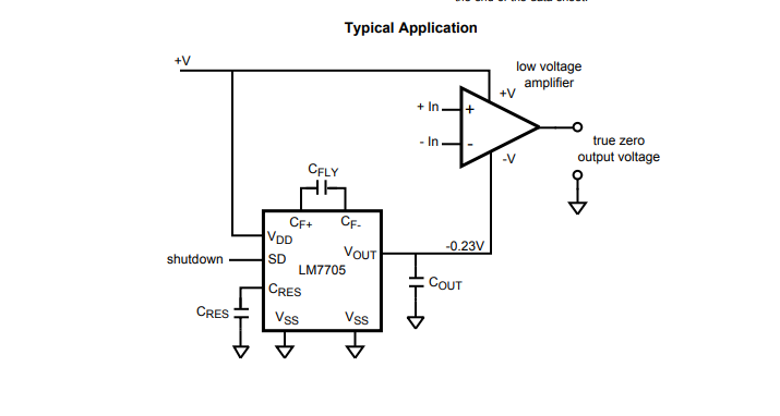
You can get a small negative voltage by using an LM7705 which produces -232mV nominal output voltage using a charge pump.

enter image description here

The advantage of using that part over a typical garden-variety inverting charge pump converter (eg. +5 to -5) or inverting boost converter is that the worst-case negative output voltage generally falls within the maximum negative input voltage of something like your ADC converter (-300mV in your case, which is typical), so you don't need to try to clamp the op-amp output/ADC input voltage near ground.

On the other hand, it's probably more expensive than some other solutions that would take more engineering effort, so this is just one of many possibilities.

\$\endgroup\$
4
  • \$\begingroup\$ How do I estimate the impact of the switching noise of the charge pump on the performance of the op-amp? Should I look at the op-amp's PSRR? \$\endgroup\$
    – axk
    Commented Mar 15, 2019 at 0:06
  • \$\begingroup\$ Output Voltage Ripple 4 mVpp 91kHz OPA365 60dB PSRR \$\endgroup\$
    – D.A.S.
    Commented Mar 15, 2019 at 0:56
  • \$\begingroup\$ Yes, Tony gave you the parameters. Of course you can filter it further if you need to. \$\endgroup\$ Commented Mar 15, 2019 at 1:07
  • 1
    \$\begingroup\$ Package has external pins on 0.5mm centers, very easy to solder in many ways. \$\endgroup\$
    – user105652
    Commented Mar 15, 2019 at 1:16
4
\$\begingroup\$

You could generate a small positive voltage, and use it as a virtual ground. Since you selected a differential ADC, its large common mode rejection can allow you to get away with a very simple way of generating that 0.2V reference voltage.

schematic

simulate this circuit – Schematic created using CircuitLab

\$\endgroup\$
-3
\$\begingroup\$

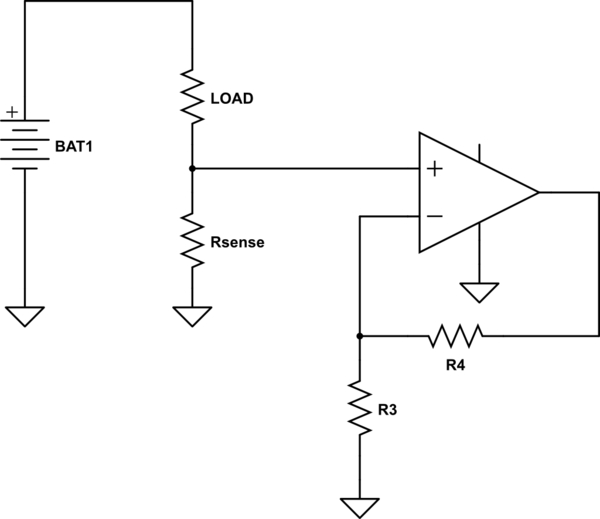
Others have given some tips, but you need to be aware that what you're trying to do a very iffy deal. The problem is that, effectively, you're trying to do

schematic

simulate this circuit – Schematic created using CircuitLab

The problem with this is that it's not accurate. You see those grounds? Trust me, at 20 amps, they are not all at the same voltage. For the current levels you're talking about, stray resistance will be a big problem. It will depend critically on pc layout and system wiring. For that matter, since copper has a rather large resistance tempco, you may have problems with temperature sensitivity due to your stray resistances changing. If you have any other part of the system which draws much current, the issue can become even worse.

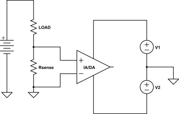
Assuming that you are using a very small sense resistor, with small voltages produced in order to avoid large power dissipation in your resistor, I would really recommend a differential measurement, also called a Kelvin connection.

schematic

simulate this circuit

where your amplifier is an instrumentation or differential amplifier.

Trust me on this, single-ended current measurement, other than very crude limit sensing, is a recipe for heartbreak. Trying to do it with a single-supply amplifier only makes it worse.

\$\endgroup\$
3
  • 3
    \$\begingroup\$ -1 The problems you state are valid, but does not solve the question at all. He is already using a differential amplifier, and he wants to know how to measure close to GND which you solved by placing V2, but you skipped how that was implemented. \$\endgroup\$
    – Linkyyy
    Commented Mar 15, 2019 at 8:07
  • 1
    \$\begingroup\$ Unless I misread the question, the OP is talking about high-side current sense, your schematic is low-side. \$\endgroup\$ Commented Mar 15, 2019 at 9:02
  • \$\begingroup\$ My understanding is that when I'm doing high-side current sensing the big current will go through the sense resistor only and I'm planning to use 5mR or 10mR 5W resistor or 2 of 10mR 5W in parallel and it rarely actually reaches the peak of 20A so I hope I should be fine. I estimate the consumption of the circuit with all digital stuff and a bluetooth transmitter should be no more than 70mA. \$\endgroup\$
    – axk
    Commented Mar 15, 2019 at 9:42

Your Answer

By clicking “Post Your Answer”, you agree to our terms of service and acknowledge you have read our privacy policy.

Not the answer you're looking for? Browse other questions tagged or ask your own question.