56
\$\begingroup\$

I am new to PCB design and I noticed that some schematics use 0Ω or 100mΩ resistors. What is their purpose and why do we need to use them in our PCB design?

Normally if we wish to probe how much current the load is taking, we put a jumper pin across the PCB trace (then measure current across the pin using a multimeter). Adding resistors for this purpose seems like it would waste a lot of PCB real-estate. Is this the sole reason why 100mΩ resistors are being placed (since I = V/0.1Ω) instead of a jumper pin?

If so, is there any consideration we should take when placing such a mΩ resistor on board so it doesn't affect the signal or behaviour of the circuit?

\$\endgroup\$
3
  • \$\begingroup\$ The 10R resistor could have all sorts of functions; without (even part of) a schematic it's impossible to say. It could be for measuring current internally on the board (in which case a high precision one will be specified). It could be a required part on the datasheet of some other part. It could be part of a resistor divider. It could be connected to an op-amp to control gain. \$\endgroup\$
    – pjc50
    Commented Oct 4, 2012 at 9:43
  • 7
    \$\begingroup\$ We are Short Circuit of Borg. Resistance is futile (if less than one Ohm). \$\endgroup\$ Commented Oct 4, 2012 at 13:07
  • 2
    \$\begingroup\$ @Dan - You mean this \$\endgroup\$
    – stevenvh
    Commented Oct 8, 2012 at 10:23

7 Answers 7

40
\$\begingroup\$

Zero Ohm "resistors" are frequently used as links on single side boards because they can be placed by component insertion machines that can insert resistors.

High volume single sided board manufacturers often use a separate link inserting machine - whose frighteningly fast speeds need to be seen to be believed.


A 1 Ohm resistor is "just another component".
It may be used as a current sense resistor or for some other circuit function.

If using resistors for current sensing for measurement purposes.

Worst case voltage drop across them should be small compared to total circuit voltage so that they do not affect operation. eg if a circuit draws 1 amp and has a 5V supply then a 1ohm resistor would drop 1 Volt. This is 20% of total circuit voltage and would be excessive in essentially all real world cases.
A 0.1 Ohm resistor would drop 0.1 V at 1A = 2% of supply and MAY be acceptable depending on circuit.
A 0.01 Ohm resistor will drop 0.01V at 1A = 0.2% and would almost always be acceptable.

The 0.1 Ohm resistor will drop 100 mV per Amp so 1 mA will produce 100 uV.
Many low cost DMMs have a 200 mV range with a resolution (but not accuracy) of 0.1 mV = 100 uV, so they can read current in a 0.1 Ohm resistor to 1 mA resolution. Similarly they can read current in a 0.01 Ohm resistor to 10 mA resolution.

Placing the sense resistors with one side grounded allows ground referenced measurement which may be convenient. The Voltage drop must not affect circuit operation.

Sometimes bypassing the sense resistor with a capacitor - maybe 10 uF or 100 uF depending on circuit, will further reduce impact on the circuit.

Where high frequency noise is present use of a DMM or other meter to measure voltage so as to calculate current will give bad results die to noise entering the meter. In such a case use an eg 0.1 Ohm sense resistor, feed the voltage via a series 1k resistor to the meter and add a say 10 uF across the meter terminals.

____________________________________

Here is a Panasonic "universal axial inserter" at work. I set the start to 35 seconds as the prior part is less consistent.

My recollection is that the wire-link-specific inserter was faster again. It fed wire from a reel, shaped, cut, inserted, cinched and cut it. ... Here we go - wow agh wow - faaaaaast wire link former inserter

@Marcelm said: "... whose frighteningly fast speeds need to be seen to be believed."_ - You're not kidding! (the video is of resistor insertion rather than links but ehh)

\$\endgroup\$
4
  • 25
    \$\begingroup\$ A zero-ohm resistor is essentially a conveniently-shaped piece of wire. \$\endgroup\$ Commented Oct 4, 2012 at 12:54
  • 3
    \$\begingroup\$ Nice and concise answer. I believe that proper terminology here is "shunts" or "shunt resistors". Those things are my favorite places stick my oscilloscope into when trying to understand what is going on. \$\endgroup\$ Commented Aug 24, 2017 at 12:01
  • 1
    \$\begingroup\$ "... whose frighteningly fast speeds need to be seen to be believed." - You're not kidding! (the video is of resistor insertion rather than links but ehh) \$\endgroup\$
    – marcelm
    Commented Sep 22, 2017 at 13:14
  • 2
    \$\begingroup\$ @marcelm :-) - and here is a Panasonic "universal axial inserter" at work. I set the start to 35 seconds as the prior part is less consistent. | My recollection is that the wire-link-specific inserter was faster again. It fed wire from a reel, shaped, cut, inserted, cinched and cut it. || Here we go - wow agh wow - faaaaaast wire link former inserter \$\endgroup\$
    – Russell McMahon
    Commented Sep 23, 2017 at 9:52
53
\$\begingroup\$

There's a huge difference between a 0 Ω resistor and a 1 Ω resistor: the latter has an infinitely larger resistance :-).

The 0 Ω has different usages:

  • selective connections. You can create variants of your circuit by placing or leaving out the jumper. Just like you would delete a connection in your schematic capture program (= remove jumper) and make a connection to a different point (= place jumper)
  • facilitate routing. A couple of jumpers over traces may allow you to use a single layer board instead of a double layer, which would cost you more. You'll typically use 0603 or 0805 size jumpers for this; 0402 are too small to bridge an average trace.
  • provide a current measurement point. During development and testing you can place a low resistance shunt resistor to measure the current, and for production replace it with a zero ohm jumper. Then you don't have to cut traces to insert the shunt resistor in the circuit. Probably less applicable, since you should have measured the current before creating the final PCB, but for very low current circuits the layout and PCB material may matter, and then you do want to measure on the final board.
\$\endgroup\$
7
  • 17
    \$\begingroup\$ Yes, but where do I find precision 0 Ohm resistors? I can only find 5% and 1%. I need more accuracy than that ;-) \$\endgroup\$ Commented Oct 4, 2012 at 13:00
  • 1
    \$\begingroup\$ @Olin - if the resistance is too low you can sell them to power perpetuum mobiles. Next go sit by your phone to wait for the call that you're nominated for The Prize. Or you can make the Mistake Of Your Life and place a higher resistance type in series with it. \$\endgroup\$
    – stevenvh
    Commented Oct 4, 2012 at 13:04
  • \$\begingroup\$ Yeah, I'm working on a microcontroller that runs a charge pump to power itself. Big klunky motors with generators won't work, but microcontrollers are getting so efficient now. It's time to take perpetual motion machines high tech! \$\endgroup\$ Commented Oct 4, 2012 at 13:07
  • 6
    \$\begingroup\$ Many PCB boards have "optional" components -- different configurations of the same basic design. It's much cheaper to design and manufacture a single PCB board/layout and then populate it differently to get the different configurations. Zero-ohm "jumpers" are use to optionally connect traces so it still works in the absence of some components or set bits that the controller can read to know the configuration. \$\endgroup\$ Commented Oct 4, 2012 at 14:08
  • 1
    \$\begingroup\$ @Olin If your 0 Ohm is made of aluminium you can help it with a dash of supercooled liquid helium. \$\endgroup\$
    – oakad
    Commented Apr 7, 2014 at 2:40
11
\$\begingroup\$

I have seen 0 ohm resistors used in calibration/testing. For example, if you put an RC lowpass on a board but realise that it isn't required, you just put a 0 ohm instead of any resistor and leave the capacitor off.

This selective building of noise reducing circuits is quite common; if you open up some commodity hardware that is relatively complex (DTV receiver for example), you might see that a lot of decoupling capacitors are left off. This is because they test the boards after manufacture, and if they are too noisy after QA, they just put more capacitors on in different places until it passes. Some extremely sensitive instrumentation devices can have a completely unique denoising circuits (as tuned by a grey-haired, bearded man of course)

Also: You can use them as a kind of soldered down DIP switch to select features for a device.

\$\endgroup\$
3
\$\begingroup\$

This is a aside relative to the question, but adds to what Russell said about low value current sensing resistors.

When using very low value resistors to measure current by generating a voltage proportional to that current, you have to consider the resistance of the connections to those resistors. One way to get around this is to do what is called a "4 wire" measurement. You run the current thru the sense resistor normally, but measure the voltage differentially with separate feed lines immediately accross the resistor. With proper differential measurement, this cancels out any additional voltage drops created by that current in the high-current connections to and from the resistor.

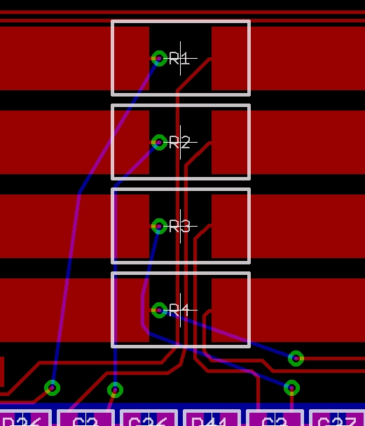
Here is a example of a 4 wire measurement:

R1-R4 are 100 mΩ current sense resistors that can carry as much as 4 amps in this case. The system needs to react to these currents at 1/4 mA resolution at the low end. The left side connections are all actually ground and are tied together shortly to the left of this snapshot. Even though most of the ground path is isolated, imagine the problem of multiple amps running thru the top three resistors and trying to distinguish between 1/4 mA and 1/2 mA flowing thru the bottom one. Those amps thru the top resistors will easily cause a ground offset at the bottom one well larger than the voltage drop caused by 1/4 mA accross R4.

The solution is the 4 wire measurement technique. Note the two wires coming from the inside connection of each resistor. Those go to what are essentially differential amplifiers that only respond to the difference of the voltage between the two wires. Those wires can be small since they are carrying little current. Their purpose is only to report the voltage to the diff amp.

\$\endgroup\$
2
  • \$\begingroup\$ Why is the reason that traces on the bottom layer have weird angles and do not go as close as possible to the matching trace on the top layer, since they will go to a differential amplifier? Is that not critical that much? \$\endgroup\$ Commented Oct 4, 2012 at 14:19
  • 2
    \$\begingroup\$ @abdullah: In some cases that would matter, but in this case the signals are very low impedance and noise pickup isn't a issue. \$\endgroup\$ Commented Oct 4, 2012 at 15:41
3
\$\begingroup\$

Planes have to be connected via a single point. Placing a 0Ω resistor between nets representing those planes helps to enforce the rule.

\$\endgroup\$
4
  • 2
    \$\begingroup\$ Er.. how is a 0 ohm resistor better here than a PCB trace between the planes?? \$\endgroup\$
    – stevenvh
    Commented Oct 8, 2012 at 10:21
  • 1
    \$\begingroup\$ Sure, if you are going to layout it's not needed. If you pass on schematics and the designer isn't paying attention they may make multiple traces. It's not better, it prevents errors. \$\endgroup\$
    – regomodo
    Commented Oct 8, 2012 at 10:29
  • 1
    \$\begingroup\$ You mean it fixes errors, not prevents them. For production this is not a solution, though. If the layout doesn't provide a location for the jumper you won't be able to place it: traces and copper pours will have solder resist over them; you have no pads. Of course you can add jumper positions everywhere on the board, but IMO it's easier to design it correctly in the first place. If you can think about needing a jumper between net A and B, then you can also think of making the connection directly if it would be needed. For a one-off PCB I would solder a wire to fix a layout error. \$\endgroup\$
    – stevenvh
    Commented Oct 8, 2012 at 10:58
  • 2
    \$\begingroup\$ Well, its the way we've done it for years in Mil apps and the way i was taught to prevent contractor mess ups. Works for us. \$\endgroup\$
    – regomodo
    Commented Oct 8, 2012 at 16:12
-2
\$\begingroup\$

From my experience the 0 ohm resistor is for current sensing or connecting a digital signal depending on the type of circuit of course. In the digital circuit it can be used to identify which signal is high or low by a bidirectional PWM

\$\endgroup\$
2
  • 5
    \$\begingroup\$ Of course there is no such thing as an actual zero Ohm resistor (at least, not one that works at room temperature.) So in reality, a part labelled as zero Ohms will have some unspecified, very small resistance. You're saying that you design circuits that rely on an unspecified resistance value for sensing current? \$\endgroup\$ Commented Feb 5, 2018 at 17:17
  • \$\begingroup\$ Hmm if you don't care about the exact resistance, why not use a zigzagged trace on the PCB instead? It'll have the same issues as a 0 ohm resistor (resistance depends on temperature and varies between boards) but that's one less component :) \$\endgroup\$
    – Navin
    Commented May 13, 2019 at 11:14
-2
\$\begingroup\$

Proven with my own experience. For zero resistance, I found physically that whenever putting a zero ohm resistor in series with the load, whereby load material is semiconductor(LED, processor, etc), the heat dissipated from load will reduce slightly, and the zero ohm resistor actually become hotter, that zero ohm resistor is sharing portion of the heat generated by load. I do not know that zero ohm resistor is made of what material, I just bought it somewhere in electronics shop and use it. I found no such result in google. However, the procedure to validate my finding is easy, just use the "thermal scanner" to scan both LED with and without zero ohm resistor, you may google thermal scanner in picture, kind of gun alike scanner. According to my own assumption, I think there is something to do with the material properties. Can you recall, the rusting always choose the zinc instead of iron when they are connected together; the heat choose the zero ohm resistor material to dissipate heat instead of choosing the LED when they are connected together, something like that. I guess nobody is doing this thus I found nothing on internet, somebody can use this as a research in university to produce some papers.

\$\endgroup\$
3
  • \$\begingroup\$ I found something on resistor power wattage, and in actual no perfect zero ohm, with that negligible ohm actually taking away internal resistance of load. I guess heat dissipated from electronics components are related to resistance or internal resistance? How to differentiate R and Rinternal? \$\endgroup\$ Commented Sep 4, 2018 at 1:45
  • 4
    \$\begingroup\$ There's no mystery about your "zero ohm" resistors getting warm. The answer is simple: those zero ohm resistors aren't really zero ohms. They are just "very close to zero ohm" resistors. Since they have a small resistance, they waste a bit of power as heat. A true "zero ohm" resistor would be a superconductor. \$\endgroup\$
    – JRE
    Commented Sep 4, 2018 at 5:15
  • 4
    \$\begingroup\$ Making an answer about things you don't understand is as usual, very fruitless. \$\endgroup\$ Commented Sep 4, 2018 at 7:25

Your Answer

By clicking “Post Your Answer”, you agree to our terms of service and acknowledge you have read our privacy policy.

Not the answer you're looking for? Browse other questions tagged or ask your own question.