0
\$\begingroup\$

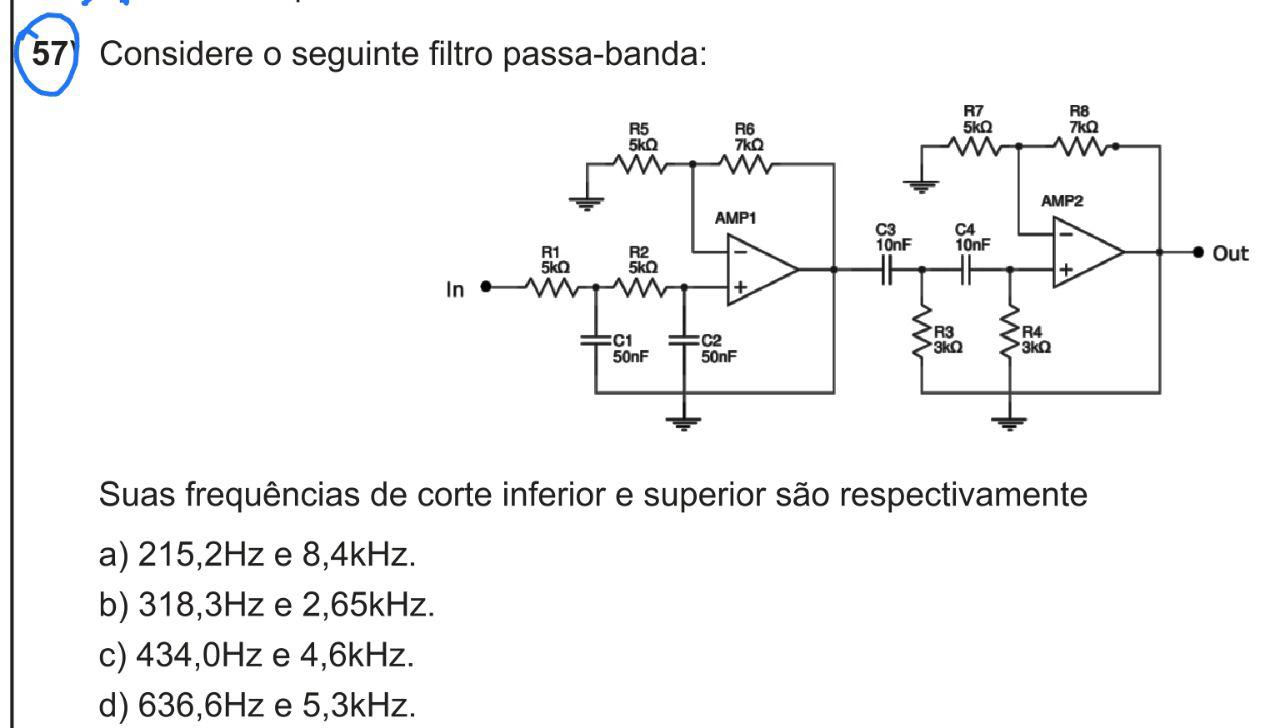
I've tried to solve this contest question regards the band pass filter (find the frequency at low-pass and high-pass filters) the picture below:

enter image description here

My attempt:

I consider that the first stage is 2 low-pass filter identically (R1 C1) and (R2 C_2) - circuit RC - \$R = 5\,k\Omega\$ and \$C = 50\,nF\$

So compute the cut-off frequency: \$ f_c = \frac{1}{2\pi R_1C_1} = \frac{1}{2\pi R_2C_2} = \frac{1}{2\pi \cdot 5\cdot 10^3\cdot 25\cdot 10^{-9}} \approx 636,6 Hz \$

Seems "ok".

Continue: when I look to the second stage I can see 2 high-pass filter (C3 and R3) and (C4 and R4)

cut-off frequency: \$ f_c = \frac{1}{2\pi R_3C_3} = \frac{1}{2\pi R_4C_4}=\frac{1}{2\pi \cdot 3\cdot 10^3\cdot 10\cdot 10^{-9}} \approx 5,3 kHz \$

The answer is letter d)

But whats about the others resistances the circuit? and when you use the same filter in series the simple question is: the frequency response has the same value when you use only 1 low-pass filter?

I tried to simulate this circuit and figure out that the frequency cut-off ( i guess) is \$0.79kHz\$ e \$4.18kHz\$

SIMULATED FREQUENCY RESPONSE

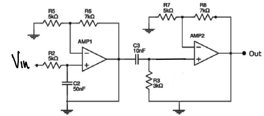
I presumed that the correct schematic this circuit to match the same \$ f_c\$ as the question required must be such as the imagem below:

enter image description here

So, anyone has any advice to solve the entire circuit and provided a decent analysis to this circuit? thanks for any hints.

\$\endgroup\$
1
  • \$\begingroup\$ The question choices were in error because it did not calculate the total loss at -3dB \$\endgroup\$
    – D.A.S.
    Commented Mar 20, 2019 at 12:42

1 Answer 1

2
\$\begingroup\$

But whats about the others resistances the circuit?

The gain setting resistors (R5, R6, R7 and R8) do two things: -

  • Set the pass-band gain
  • Modify the Q of the circuit enabling a peak in the frequency response around the cut-off frequency of each stage.

when you use the same filter in series the simple question is: the frequency response has the same value when you use only 1 low-pass filter?

With equal values for R1 and R2 AND C1 and C2 then the cut-off frequency is the same for a single order low pass filter. The big difference in your circuits (Sallen Key, 2nd order filters) is that any signals that are outside the pass-band are attenuated to a greater extent.

If you are asking about the change in the 3 dB point of the low-pass filter when you introduce the high-pass filter then sure, there'll be some interaction and that interaction gets worse as the two cut-off frequencies get closer. With the two cut-offs at 637 Hz and 5.3 kHz, there will be some slight interaction.

Your final circuit diagram is wrong and makes no sense. You have op-amp outputs connected to ground and that is a spoiler.

\$\endgroup\$

Your Answer

By clicking “Post Your Answer”, you agree to our terms of service and acknowledge you have read our privacy policy.

Not the answer you're looking for? Browse other questions tagged or ask your own question.