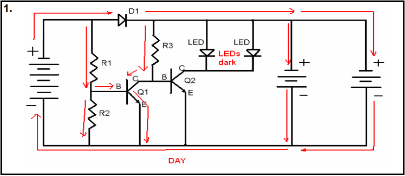
Assuming the + and - of the batteries are correct and not the polarity shown by the battery symbols (the long line is the +, short line is -) and also assuming that the battery voltages are such that D1 isn't destroyed then:
It depends on the values of R1, R2 and R3 what mode of operation Q1 will be in.
If Q1 operates in active mode then it will have a large enough Vce to enable some current (coming from R3) to flow into the base of Q2. As the LEDs are indicted as not lighting up, we can assume that this is not the case.
If Q1 operates in saturation mode then Vce will be much smaller, typically less then 0.4 V which will prevent any current to flow into the base of Q2. For a current to flow into the base of Q2 there needs to be more than about 0.6 V across the base-emitter of Q2.
This isn't a well designed circuit. If Q2 would conduct then it also determined the current through the LEDs which (depending on Q1 and resistors) could be high enough for the LEDs to conduct too much current. There should have been resistors in series with the LEDs.

