2
\$\begingroup\$

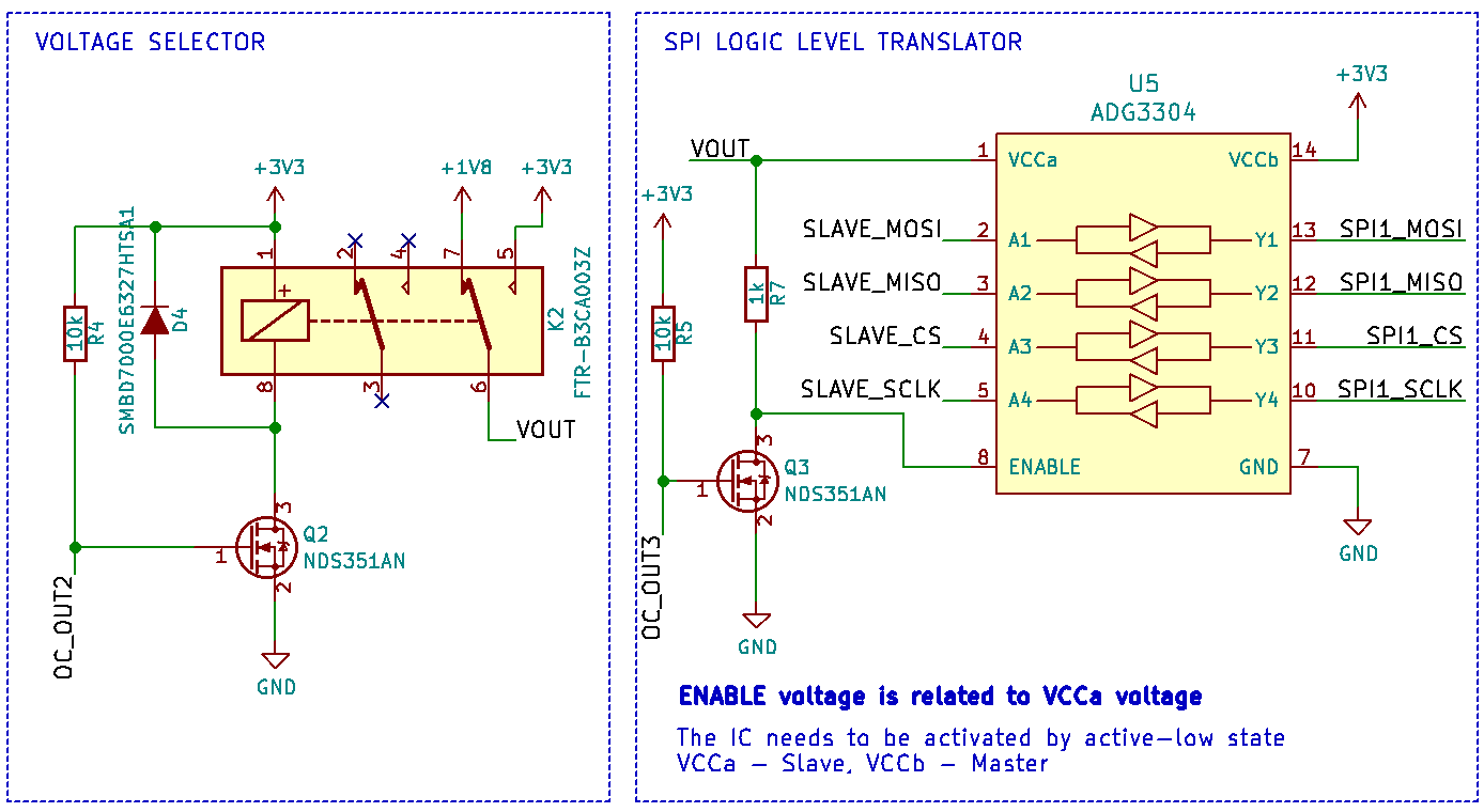
Have you ever had any experience with an ADG3304 IC? I've prepared a circuit which allows to translate logic levels in SPI interface.

I want my circuit to be compatible with both 1.8V and 3.3V logic levels. That's why I used a relay for selecting the output voltage. My master device is attached to Y-signed pins and slave is opposite. My problem is that I can't communicate with neither 3.3V nor 1.8V-supplied slaved-devices. The circuit of the voltage selector works good.

What could be a possible issue?

enter image description here

I used a logic analyzer to check periods. The first screen is wrong communication

enter image description here

This one is correct:

enter image description here

I tried 3 another methods: - I added decoupled capacitors near VCCa any VCCy (100 nF) - CS pin has been pulled up to VCC via a 10k resistor - Voltage divider has been created on a MISO line with 2 10k resistors

Still no results. SPI doesn't work

\$\endgroup\$
8
  • \$\begingroup\$ SPI mode could be an issue. Hook up a scope to your CS, CLK and SDA pins, and check your timing diagrams in datasheets of the devices you are trying to communicate with. See if they match \$\endgroup\$ Commented Mar 27, 2019 at 11:18
  • 2
    \$\begingroup\$ Absolute maximum ratings state \$ VCCY \leq VCCA\$ Operating on the edge of the abs max ratings is not recommended. First page of datasheet: For proper operation, VCCA must always be less than VCCY. Further, did you use decoupling capacitors? \$\endgroup\$
    – Huisman
    Commented Mar 27, 2019 at 11:18
  • \$\begingroup\$ You have left out all the important parts of the circuits. What is the OC_OUT3 signal? Have you read the sections "input driving requirements" and "output load requirements" of the datasheet? \$\endgroup\$
    – CL.
    Commented Mar 27, 2019 at 11:37
  • 1
    \$\begingroup\$ @Huisman That's strong enough to be an answer. \$\endgroup\$
    – DKNguyen
    Commented Mar 27, 2019 at 19:13
  • 1
    \$\begingroup\$ @Huisman So you're saying it should be at least working with Vcca = Vccy = 3.3V? Either way, I think it's still valid as an answer since if OP wants it to run at 1.8V and 3.3V, they will need to make corrections anyways. And lack of decoupling caps could easily explain why it's not working when everything is 3.3V \$\endgroup\$
    – DKNguyen
    Commented Mar 27, 2019 at 22:02

1 Answer 1

1
\$\begingroup\$

As discussed in the remarks, you can operate the IC with Vcca = Vccy = 3.3V.
But make sure your circuit satisfies the description given in POWER SUPPLIES on page 17 of the datasheet. So, power VCCY first and then VCCA, and decouple the VCCA pin and VCCY pin to GND as close as possible to the device.

I'd also advise to get rid of the relay and replace it by (high side) mosfets. This enables you to enable Vout (whether it is 1.8V or 3.3V) after 3.3V is powered up. You could e.g. implement a supervisor IC to enable Vout.

\$\endgroup\$
1
  • \$\begingroup\$ in my design, VCCy voltage is attached to 3.3V for good. To make it clear, my master device is an SPI interface within an OrangePi platform and is attached to Y-side pins. It is because I want my device to handle both 1.8V- and 3.3V-supplied devices, mainly Flash memory. \$\endgroup\$ Commented Apr 1, 2019 at 7:52

Your Answer

By clicking “Post Your Answer”, you agree to our terms of service and acknowledge you have read our privacy policy.

Not the answer you're looking for? Browse other questions tagged or ask your own question.