1
\$\begingroup\$

I am creating a power supply as a small project. I am planning on using two transformers (in parallel) to create a positive rail and a negative rail. Will this cause a problem ?

I have researched online and found that the transformers can be connected in parallel given that they have the same number of turns and are in phase.

Both the transformers will be connected to the same AC outlet thus I assume they would be in phase ?

Also both the transformers are 220VAC to 12VAC , but one of them is rated for 1 A(planning to use that for +ve rail) while the other is rated for 500mA. Will this cause a problem ?. I assume not since they would both have the same no of turns (the 1 A transformer may have thicker windings ?)

If there will be a problem , is there any way to connect two transformers to the same AC source ?.

I have attached the schematic below if it helps.

Thanks for your help :)
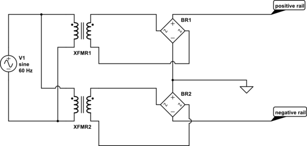
schematic

simulate this circuit – Schematic created using CircuitLab

PS : Is my schematic correct? I think this is how to create a negative voltage rail.

Edit : Fixed typos, reworded a part of the question

\$\endgroup\$

3 Answers 3

6
\$\begingroup\$

I am planning on using two transformers (in parallel) to create a positive rail and a negative rail. Will this cause a problem?

No. The primaries are in parallel as they should be. The secondaries are not.

I have researched online and found that the transformers can be connected in parallel given that they have the same number of turns and are in phase.

That would be a requirement if you were connecting the secondaries together at both ends. You're not in this case and it would not be unusual to have different voltage requirements for the positive and negative rail and so different transformer secondary voltages would be used.

Both the transformers will be connected to the same AC outlet thus I assume they would be in phase?

That depends on internal and external wiring of and to the coils but in this case it doesn't matter. At the output of the bridge rectifiers is a 100 Hz (assuming 50 Hz supply) full-wave rectified signal. This will be the same regardless of the input or output phasing.

Also both the transformers are 220 V AC to 12 V AC , but one of them is rated for 1 A (planning to use that for +ve rail) while the other is rated for 500 mA. Will this cause a problem? I assume not since they would both have the same no of turns (the 1 A transformer may have thicker windings ?)

Your assumption is correct but your reasoning is not. As discussed above, your two rectified supplies are independent and only connected at one point. An analogy is a 12 V car battery for your positive supply and a small 9 V battery for your negative supply. If the 9 V battery can provide the required current on its load then that's all you need.

Is my schematic correct? I think this is how to create a negative voltage rail.

Yes. You'll probably be adding in some capacitors to smooth it out.

\$\endgroup\$
1
  • \$\begingroup\$ Thank you I understand now and yes I will be adding capacitors to smooth out the voltage, this was just a quick basic schematic to get my question across clearly :) \$\endgroup\$ Commented Mar 30, 2019 at 20:35
2
\$\begingroup\$

That schematic looks fine. I assume you are going to add reservoir capacitors between the rails and ground to hold up the output rail between peaks of the input waveform!

The fact that the transformers are different current ratings is not a problem, as long as you don't exceed the respective rating on either rail. Note that with a diode/capacitor supply, you should derate the transformer's rated current for output DC current, to about 85% IIRC, I'm sure someone can look it up and correct me.

While you have got the primaries connected in parallel, that's no more than connecting them both to the same mains supply. Everything connected to mains is connected in parallel.

You have not connected the transformers 'in parallel', the secondaries are totally isolated from each other. They could safely be different voltages, you could invert the phase on one, with no problems.

If you had connected the secondaries directly in parallel, then you would need to make sure that not only were they the same nominal voltage, but also had exactly the same number of turns, primaries and secondaries, and were phased correctly.

\$\endgroup\$
1
  • \$\begingroup\$ Thank you :) and yes I will be adding capacitors to smooth out the output of the rectifier. Edit : As for derating I would probably draw a absolute max current of 300 mA if even that. I am using a 1A transformer on the +ve rail just in case I need to have higher current needs in the future. \$\endgroup\$ Commented Mar 30, 2019 at 20:39
1
\$\begingroup\$

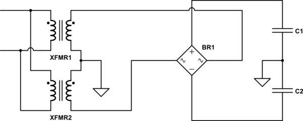
There's nothing wrong with your proposed circuit, but if the transformers are identical, and if you make sure that they're connected in the correct phase, you can improve on it a bit by using just one bridge rectifier.

See the schematic. You could also use a center-tapped transformer, if you have one of the appropriate voltage.

schematic

simulate this circuit – Schematic created using CircuitLab

\$\endgroup\$
1
  • \$\begingroup\$ The circuit is correct for identical transformers, but the OP has said that they have different transformers so this circuit is not appropriate for their situation. \$\endgroup\$
    – EinarA
    Commented Mar 31, 2019 at 3:32

Your Answer

By clicking “Post Your Answer”, you agree to our terms of service and acknowledge you have read our privacy policy.

Not the answer you're looking for? Browse other questions tagged or ask your own question.