2
\$\begingroup\$

I am a new learner of electronic.

  1. I am trying to modified a H-bridge motor driver circuit to control a thermoelectric cooler. Since I want to use PWM to control mosfets ON/OFF duration, in order to control the input voltage of the thermoelectric cooler. I want the circuit can output a smooth voltage then I use the LC filter, but I don't know how to calculate the value of L & C.
  2. I try to use 16V,180uF capacitor series with another 16V,100uF capacitor and in parallel with the thermoelectric cooler, it turns out that mosfets are damaged. Can I just capacitor to do the voltage smoothing? If yes, how can I determine what's the value of the capacitor I should use?

the circuit is similar to this:
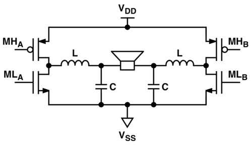
enter image description here

PS: The maximum voltage of the thermoelectric cooler is 12V (dc) and maximum current will be 12A, the maximum output frequency of micro controller is 1MHz.

\$\endgroup\$
4
  • \$\begingroup\$ The 4-pole filter is unnecessary, a simple LC is enough. Use the motor's current maximum ripple to get the L's value and the desired ripple for the C. If the motor has a high enough inductance and time constant, you could even drive it directly, but that's only if. Of course, in addition to the filter, you may also need (most likely) a good feed-back loop, that's why the lesser the poles, the better. \$\endgroup\$
    – Vlad
    Commented Oct 7, 2012 at 16:55
  • \$\begingroup\$ thank you for your answer, since thermoelectric cooler is not an inductive device and the maximum supply voltage is 12V(dc), current is 12A. I think I can't use V=L(di/dt) to calculate it. about the C value I can't use i=C(dV/dt). any equation I can use to approximate the value of L & C? \$\endgroup\$ Commented Oct 8, 2012 at 13:35
  • \$\begingroup\$ Meiling, I admit I actually thought your device makes use of a motor, my apologies for that. However, now I have to also admit I don't know how such a device acts in a circuit, so I can't give any advice on that. But, if the device only needs \$\pm\$DC to be work, then it's all a matter of designing a bridge buck converter for which you could start by searching for "Designing with TL5001" as a reference. If it needs AC and you're using the PWM to modulate an AC signal, then use the links Russell McMahon gave you, they're good. I'll stop now, hopefully I actually transmitted a good message :) \$\endgroup\$
    – Vlad
    Commented Oct 8, 2012 at 16:09
  • \$\begingroup\$ Thank you Steven! I am checking out the links given by McMahon and I found some helpful information. Thank you so much for your help again! \$\endgroup\$ Commented Oct 9, 2012 at 4:50

1 Answer 1

1
\$\begingroup\$

You do not need to drive it with a conventional AC switched H bridge - you want net DC of one polarity for heating and of the other for cooling.

You can eg turn MLB on DC and PWM MHA to get one polarity, and eg MLA, MHB for the other. Effectively you have a buck converter. Vdc = Vdd x duty cycle.


TI SLOA023 - Reducing and eliminating the Class D output Filter

Related

Of use, but your load is non inductive, so not wholly applicable.

Fres = 1 / (2 Pi sqrt(LC))
Impedance = 2 Pi sqrt (L/C)

Useful

Wikipedia - Class D amp

\$\endgroup\$
1
  • \$\begingroup\$ Thank you Russell, when I check out the links you give me, I know more about the filter especially the first link. It mention how to calculate the current across inductor. Do you think that I need to decide what frequency first (if it is, what frequency would you recommend), then use the equation 8 provide by [ TI SLOA023 - Reducing and eliminating the Class D output Filter ] to calculate the inductor value then calculate the capacitor value? [I am really a novice of electronic, I am apologize for any unclear explain of my situation.] Thank you for your help! \$\endgroup\$ Commented Oct 12, 2012 at 15:24

Your Answer

By clicking “Post Your Answer”, you agree to our terms of service and acknowledge you have read our privacy policy.

Not the answer you're looking for? Browse other questions tagged or ask your own question.