0
\$\begingroup\$

I am designing my own PCB around a PIC32MM0064GPL028 microcontroller. Breaking down the steps below-

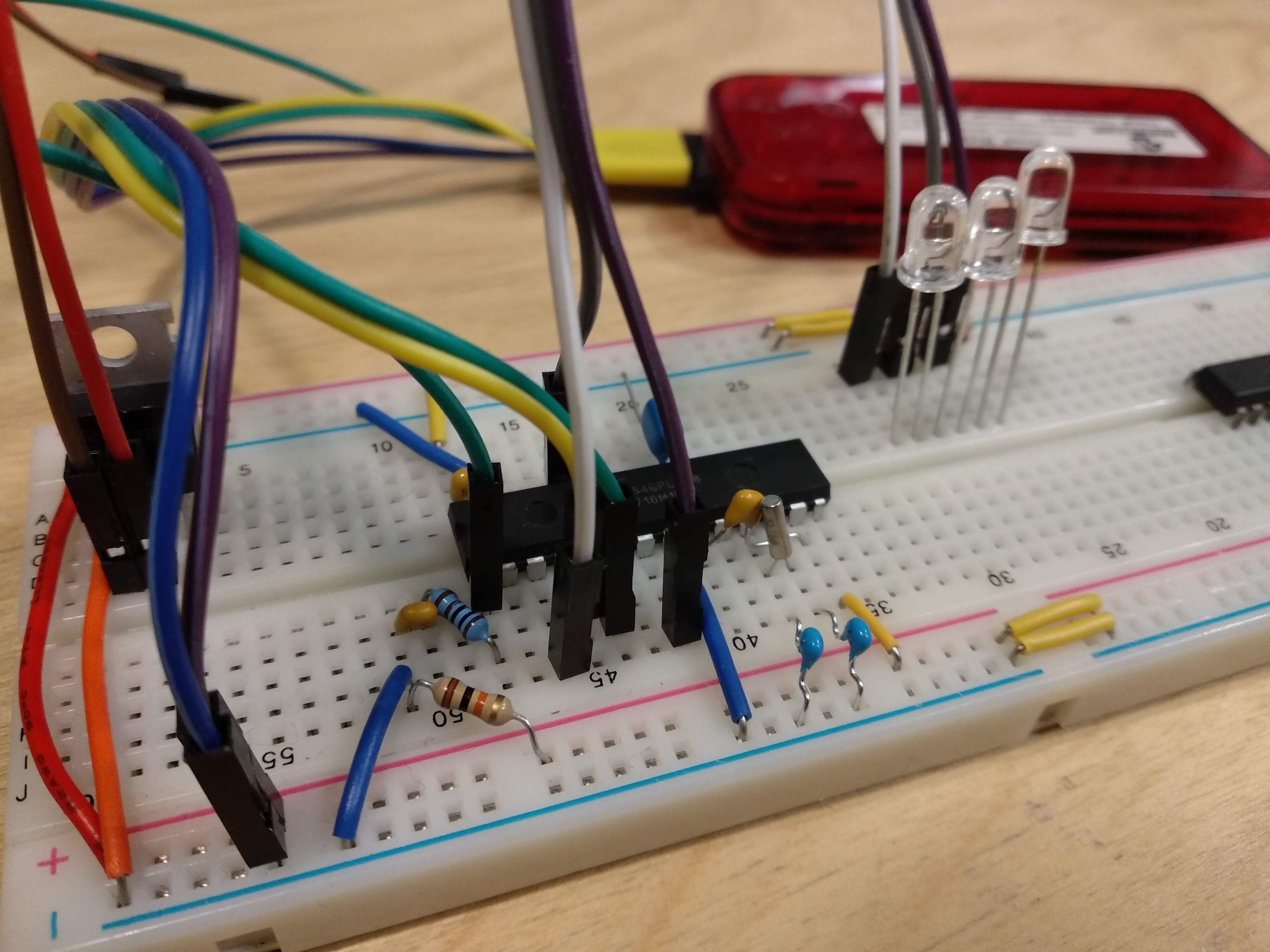
  1. I have built a simple breadboard version first, inspired by PIC32MM curiosity development board.Breadboard(updated)
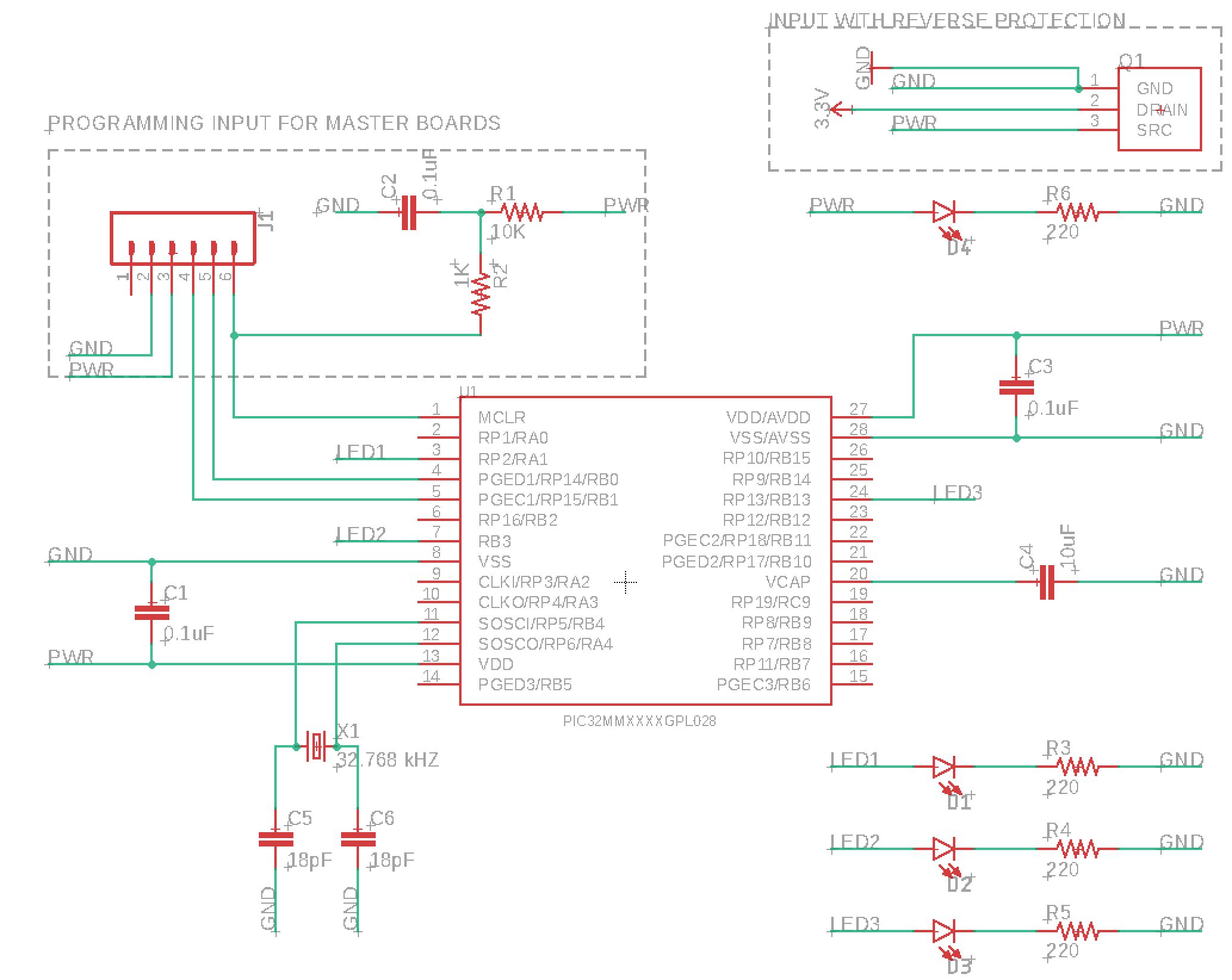
  2. Here is the schematic of the prototype programmed using PicKit3.Schematics
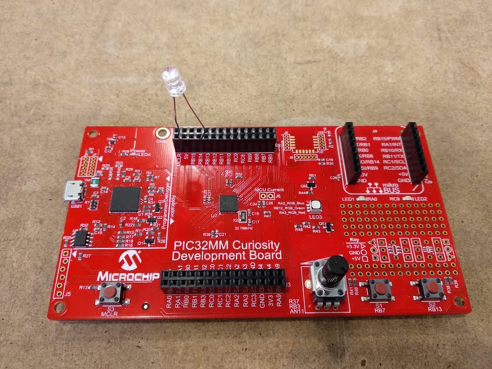
  3. The prototype connects and programs with no issues. And the same code works perfectly on the curiosity development board. This indicates that the issue is in the schematics or components. PIC32MM curiosity development board
  4. Links to the components I am using - PIC32, crystal, 18pF capacitor for crystal, 10uF capacitor for Vcap, Reverse Protection mosfet.

I am not an electronics engineer and have been playing with arduino and similar boards for quite a while now. However, this is all very new to me and probably the issue is a silly one. It'll be super helpful if you could help me debug the issue. I can upload the code if it helps? Thanks.

\$\endgroup\$
8
  • 2
    \$\begingroup\$ Shouldn't the LED on the development board have a resistor in series as well? And why is it connected to MCLR? You may have damaged RB13 as it should not exceed the abs max ratings (chapt 26.0 datasheet) \$\endgroup\$
    – Huisman
    Commented Apr 2, 2019 at 9:57
  • \$\begingroup\$ The LED on the development board is working fine even without the resistor (although a resistor is recommended, you are right). The problem is in the breadboard circuit (resistor included) which is not triggering the led. \$\endgroup\$
    – Dhruv
    Commented Apr 2, 2019 at 10:14
  • \$\begingroup\$ What voltage do you measure on pins 3, 7 and 24? If you measure 3.3V, check the polarity of the LEDs. \$\endgroup\$
    – Huisman
    Commented Apr 2, 2019 at 10:17
  • 1
    \$\begingroup\$ @Dhruv The series resistor is not just recommended, it is required. Otherwise you WILL damage your LEDs and/or your PIC \$\endgroup\$
    – DerStrom8
    Commented Apr 2, 2019 at 10:35
  • 1
    \$\begingroup\$ Downvote for all the time wasted because of a circuit diagram that was an inaccurate draft. \$\endgroup\$ Commented Apr 2, 2019 at 13:14

3 Answers 3

3
\$\begingroup\$

It looks like you made a mistake in your schematic: PIN 8 of the PIC (VSS) is connected to PWR and PIN 13 of the PIC (VDD) is connected to GND. VDD must be tied to the power, and VSS to the GND. What is the voltage of PWR? Why don't you use 3V3 for MCLR and VDD/AVDD?

\$\endgroup\$
3
  • \$\begingroup\$ Yeah, sorry about that mistake in the schematic. The actual circuit itself has the right connection though. PIN13 to pwr and VSS to GND. It is 3.3V as shown in the top-right part of the schematic, protected by a reverse current protection circuit. \$\endgroup\$
    – Dhruv
    Commented Apr 2, 2019 at 10:12
  • 1
    \$\begingroup\$ Please update your schematics to the correct version. \$\endgroup\$
    – Huisman
    Commented Apr 2, 2019 at 10:19
  • \$\begingroup\$ schematic updated. Sorry about that. \$\endgroup\$
    – Dhruv
    Commented Apr 2, 2019 at 10:45
1
\$\begingroup\$

turns out it was just an incorrect connection to MCLR pin. I connected the 10k resistor in the wrong position in the breadboard. The schematics are fine and the prototype is working now. Thanks a lot for helping and let me know if you want me to share something else.

\$\endgroup\$
2
  • \$\begingroup\$ Congrats for finding it. This error was hardly detectable from the initial picture in your post. For next questions, I'd recommend providing clear pictures (from different angles, showing the whole setup etc) and correct schematics. Good luck with this board! \$\endgroup\$
    – Huisman
    Commented Apr 2, 2019 at 11:37
  • \$\begingroup\$ Thanks. You are right, I was assuming the issue is in the schematic itself, or the components I am using. No assumptions next time! Thanks. \$\endgroup\$
    – Dhruv
    Commented Apr 2, 2019 at 11:40
0
\$\begingroup\$

There is nothing connected to pin 3 (LED1) of the PIC on your breadboard, neither to pin 7 (LED2). Double check your connections.

\$\endgroup\$
1
  • \$\begingroup\$ Yeah I was just trying to different pins for output and must have moved them around before the picture. It's updated now, apologies again. \$\endgroup\$
    – Dhruv
    Commented Apr 2, 2019 at 11:14

Your Answer

By clicking “Post Your Answer”, you agree to our terms of service and acknowledge you have read our privacy policy.

Not the answer you're looking for? Browse other questions tagged or ask your own question.