0
\$\begingroup\$

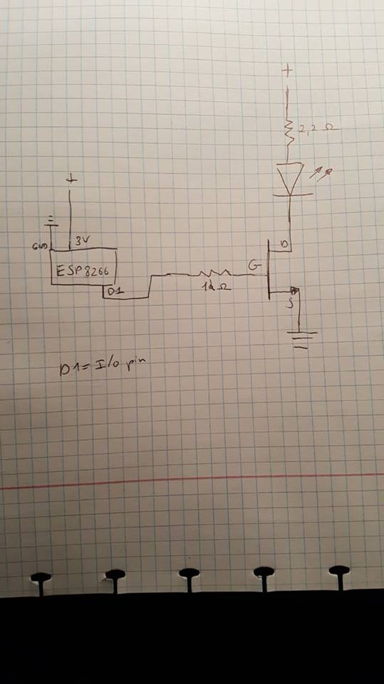
I'm building a project that uses a high power LED (3 Watt) in connection with an ESP8266 module using the module as an access point and connecting to it with my smarthpone. I've successfully managed to switch the led on and off with my smartphone and connecting the I/O pin to a logic gate MOSFET using a simple LED circuit with just a resistor and the MOSFET.enter image description here
Now though I want to have a better and more efficient circuit for driving my LED and came up with this the 1A constant current supply is supposed to be a 3.7v lithion ion battery but i didn't know how to use that with the program I used to make the circuit so by no means is the current supply constant(see image)enter image description here This isn't my own design, I found it online, the reason why it's better is this:
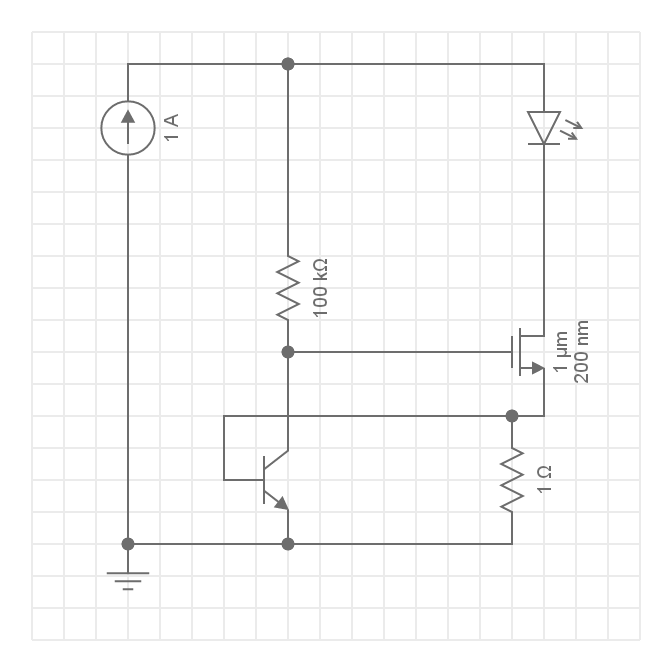
" Q2 (a power NFET) is used as a variable resistor. Q2 starts out turned on by R1.

  • Q1 (a small NPN) is used as an over-current sensing switch, and R3 is the "sense resistor" or "set resistor" that triggers Q1 when too much current is flowing.

  • The main current flow is through the LED's, through Q2, and through R3. When too much current flows through R3, Q1 will start to turn on, which starts turning off Q2. Turning off Q2 reduces the current through the LED's and R3. So we've created a "feedback loop", which continuously monitors the LED current and keeps it exactly at the set point at all times. transistors are clever, huh!

  • R1 has high resistance, so that when Q1 starts turning on, it easily overpowers R1.

  • The result is that Q2 acts like a resistor, and its resistance is always perfectly set to keep the LED current correct. Any excess power is burned in Q2. Thus for maximum efficiency, we want to configure our LED string so that it is close to the power supply voltage. It will work fine if we don't do this, we'll just waste power. this is really the only downside of this circuit compared to a step-down switching regulator!

setting the current!

the value of R3 determines the set current."

The problem now is I don't know how to use my ESP8266 again as a switch because I don't know where to connect the I/O pin where as previously I connected it to the MOSFET and basically used it as a switch but in my current circuit I don't know where to connect the I/O pin

This is my full setup for the project with the old LED circuit enter image description here
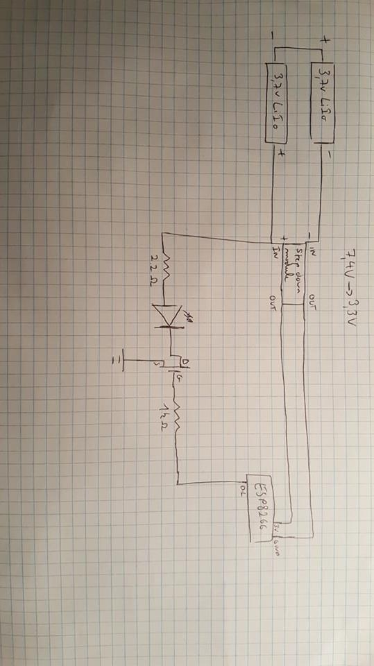
I have an additional question about this setup : is it the best way to power both the LED and the ESP8266 using a step down converter in the way I used it?

\$\endgroup\$
5
  • \$\begingroup\$ What is your goal here? What makes you think the new circuit is better? It is still wasteful, anything not switch mode would be. \$\endgroup\$ Commented Apr 10, 2019 at 23:51
  • 1
    \$\begingroup\$ Your circuit is not more efficient. It just splits the same amount of waste heat between the MOSFET and the 1\$\Omega\$ resistor, for the same LED current. It may or may not keep the LED current more constant as the battery voltage drops. \$\endgroup\$ Commented Apr 11, 2019 at 0:03
  • \$\begingroup\$ The use of a current source means the circuit cannot be turned off, as the voltage will rise until the 1amp current goes somewhere. Needless to say, this circuit is mistaken, and not something you can actually build. \$\endgroup\$ Commented Apr 11, 2019 at 0:09
  • \$\begingroup\$ What is the forward voltage of the LED as you intend to run it? \$\endgroup\$
    – Paul Uszak
    Commented Apr 11, 2019 at 0:24
  • \$\begingroup\$ 2.8 volts and peak current of 750mA \$\endgroup\$
    – B913
    Commented Apr 11, 2019 at 0:26

2 Answers 2

1
\$\begingroup\$

I'm not quite sure why you categorise the new circuit as better and more efficient. Where to connect the controller is a good question. I would suggest that you don't.

Your original circuit is almost the standard method for this 3W use case. You could add a 100k resistor between the gate and ground. This gives you some confidence of the start up state of the MOSFET as it may have accumulated charge. Since it worked, we can infer that the necessary MOSFET gate drive is < 3 V. Your incorporation of the 2.2 Ohm resistor prevents thermal runaway in most cases.

A 1A constant current supply is by no means more efficient in terms of design and parts. Especially if you only have 3V to play with. So why mess with it?

\$\endgroup\$
6
  • \$\begingroup\$ I've edited my post to explain, the thing is I don't want to buy an expensive LED driver for my circuit but the first circuit I used isn't the best because a lot of power is wasted if I just use a resistor in series with the LED \$\endgroup\$
    – B913
    Commented Apr 10, 2019 at 23:57
  • 1
    \$\begingroup\$ Your second circuit also has a resistor in series with the LED, it is just labeled as an FET. It's also unclear where you're going to get a current source, how that is implemented is what will make or break this. \$\endgroup\$ Commented Apr 11, 2019 at 0:05
  • \$\begingroup\$ I've made a mistake in the circuit by showing a 1A constant current source, it's meant to be a 3.7v lithium ion battery so the power source's current is not constant \$\endgroup\$
    – B913
    Commented Apr 11, 2019 at 0:10
  • \$\begingroup\$ @B913 then you're back to no efficiency improvement at all, just perhaps more consistent output. \$\endgroup\$ Commented Apr 11, 2019 at 0:11
  • \$\begingroup\$ Alright so you're saying I will have to use a LED driver for the power LED, there's no way around it with circuits like the one I have? \$\endgroup\$
    – B913
    Commented Apr 11, 2019 at 0:16
0
\$\begingroup\$

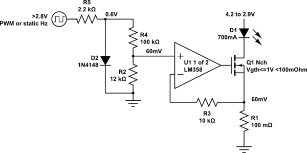
The problem with the original idea with 1 cell is the battery operates down near 3V or so and the LED operates from 3.2 to 2.9V depending on datasheet specs. This means using Vbe to sense current across 1 Ohm is too much voltage drop.

100 mOhm is more appropriate.

This will be a good tradeoff from the option to buy a buckboost LED CC driver to the efficiency of a simple FET CC regulator.

600mA~700mA Constant Current Sink low voltage drop

schematic

simulate this circuit – Schematic created using CircuitLab

Adjust R2 voltage to regulate current across 100mOhm.

You can also replace diode with Yellow LED 2mA at 2V with adequate brightness using R5 = ~680 ohm and scale down to same Vin-.

If you need more mAh then shunt matched cells together when at the same voltage.

I intentionally reduced your 3W LED to 2W but if you are confident your heatsink is adequate not to burn to touch and can accept a short battery discharge time, you can go for 1A.

\$\endgroup\$
2
  • \$\begingroup\$ Alright thanks! one of the problems I also had was the heat buildup in the mosfet when using my first circuit, will this be lower with this circuit? \$\endgroup\$
    – B913
    Commented Apr 11, 2019 at 17:58
  • \$\begingroup\$ The heat buildup is from using too high a battery voltage and VI=Pd dissipation in the FET. Using a 2P instead of 2S string of cells may work better with a 0.1V drop or less by design to operate efficiently. If you used a 2S cell from 5 to 8V then you would need some Buck regulator to regulate more efficiently eg. 1A @ 2.8 to 3.1V range for a good Samsung LED 3W chip but you didn't ask for the ideal solution.or give specs \$\endgroup\$
    – D.A.S.
    Commented Apr 11, 2019 at 18:14

Your Answer

By clicking “Post Your Answer”, you agree to our terms of service and acknowledge you have read our privacy policy.

Not the answer you're looking for? Browse other questions tagged or ask your own question.