I am currently working on a Bluetooth project which needs micro USB for charging a battery. My original plan was to use a female surface-mount micro USB socket and connect its +5v and ground pins to my Bluetooth module's battery charger. However, after seeing how tiny the pins were on the sockets available at my local electronics store, I decided it would be tedious to work with in a non-SMD application. I instead opted to use a Micro USB female to male extension lead, which I would strip, connecting the relevant +5v and ground wires to the module.
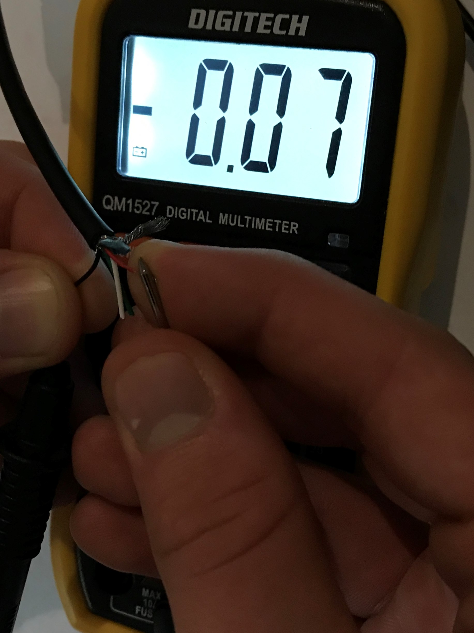
After stripping the cable, I connected it to a USB power-bank used a voltmeter to ensure I was going to solder the correct wires to the module. I ran into an unexpected problem: There was no voltage across the Red and Black wires which diagrams I found on the internet said were for +5v and ground respectively. This same issue occurred when I used other power sources.
That image might be a little hard to see, but I have the +5v and ground wires connected to the voltmeter and it reads an insignificant voltage.
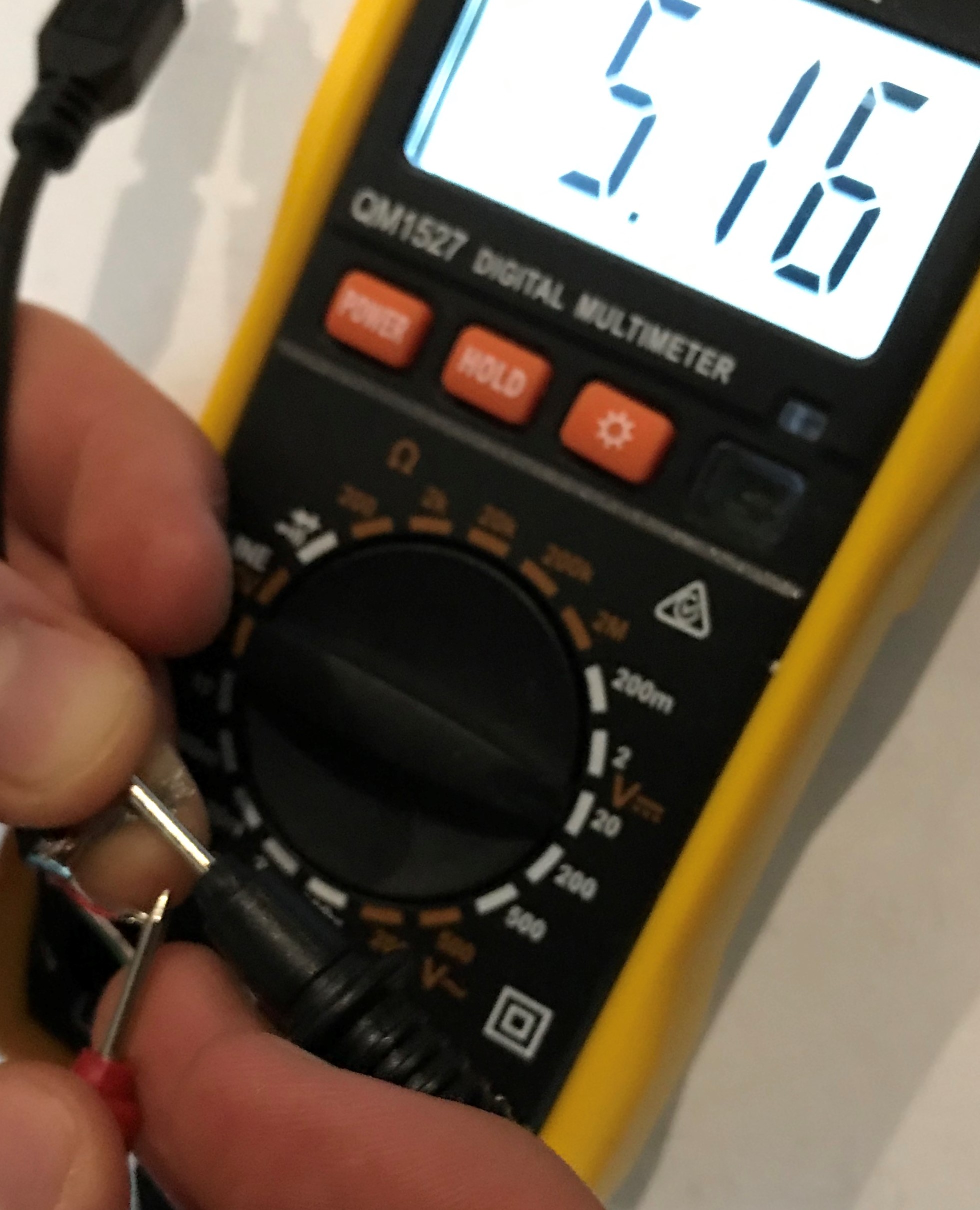
Interestingly, after some experimentation, I found that connecting the shield wire (instead of the black wire) to the negative lead of the volt meter gave 5 volts.
I had the same result no matter the device I connected the USB cable to. Should I go ahead and solder the shield and red wires to the module because they work, or is there something I'm missing which could result in ruining the board? Also, If I decide to connect the green and white data wires to the module (which can act as a USB slave) how should I wire it then?


