4
\$\begingroup\$

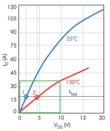
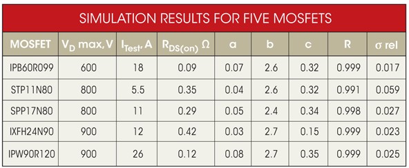
I have a question regarding an article/paper I have read (https://www.electronicdesign.com/power/analyze-mosfet-parameter-shifts-near-maximum-operating-temperature) and hope someone can help me here. In this article the author describes an equation for the drain-source on-state resistance of a MOSFET as a function of temperature and drain current. Unfortunately, I am too stupid to understand a small but important step of the author. It is about the resistance coefficient a of equation 6. The author says "a is a resistance coefficient derived from the Point 1 voltage and current (Figure 2, at 25°C)", but I don't understand how exactly, he determines this coefficient. I tried some calculation, but I don't get the same results for a like the author (listed in table "SIMULATION RESULTS FOR FIVE MOSFETs" in the article/paper).

Has anyone read this article or understands the author at once? Many thanks in advance!

\$\endgroup\$

2 Answers 2

1
\$\begingroup\$

It looks like they are using this data:

enter image description here

At 'Point 1' they divide Vds by Id to get the values in this chart:

enter image description here

In this case, for the first one, values of maybe 1.4 V and 20 A.

\$\endgroup\$
3
  • 1
    \$\begingroup\$ That's what I thought too. But if I take point 1 (as described in the paper) as reference point, then I have a current of exactly 18A (specification of the data sheet) and a drain-source voltage of about 1.4-1.5 V. The value for a from the table (0.07) would not fit. The author says about the blue curve: "The blue curve represents the drain characteristic for 25°C. The red one is for 150°C. Both curves are for the 10-V gate voltage. The manufacturer’s datasheet also provides two RDS(on) values, measured at ITest = 18 A for 25°C and 150°C shown as small circles #1 (0.09 Ω) and #2 (0.23 Ω)". \$\endgroup\$
    – Noah
    Commented Apr 30, 2019 at 15:32
  • \$\begingroup\$ Perhaps it is 1.3 V then? \$\endgroup\$ Commented Apr 30, 2019 at 15:57
  • \$\begingroup\$ I have printed out all data sheets of the MOSFETs given in the table and checked them exactly. With the other MOSFETs you can see more clearly that the author could not have used the value of Vds for determining a. \$\endgroup\$
    – Noah
    Commented May 2, 2019 at 9:25
0
\$\begingroup\$

In figure 2, there is a point marked 1. They derived the resistance from the voltage and current at that point using Ohm's law

\$\endgroup\$
3
  • \$\begingroup\$ But that would result in: R = Vds/Id = 1.5 V/18 A = 0.083 A. :/ \$\endgroup\$
    – Noah
    Commented Apr 30, 2019 at 15:35
  • 1
    \$\begingroup\$ Where are you getting the Vd=1.5V from? I don't see where the author specifies the value they used. \$\endgroup\$
    – Charles H
    Commented Apr 30, 2019 at 16:18
  • \$\begingroup\$ I read it from the diagram. \$\endgroup\$
    – Noah
    Commented May 2, 2019 at 9:25

Your Answer

By clicking “Post Your Answer”, you agree to our terms of service and acknowledge you have read our privacy policy.

Not the answer you're looking for? Browse other questions tagged or ask your own question.