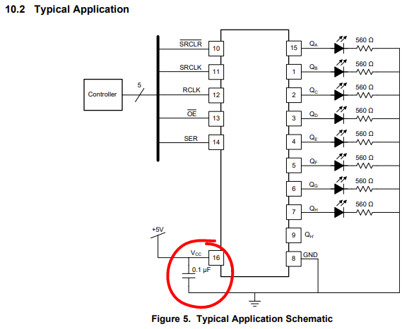
I'm picking up a weird bug with my 74HC595 Shift Register's latch pin (Datasheet).
What do I want to do?
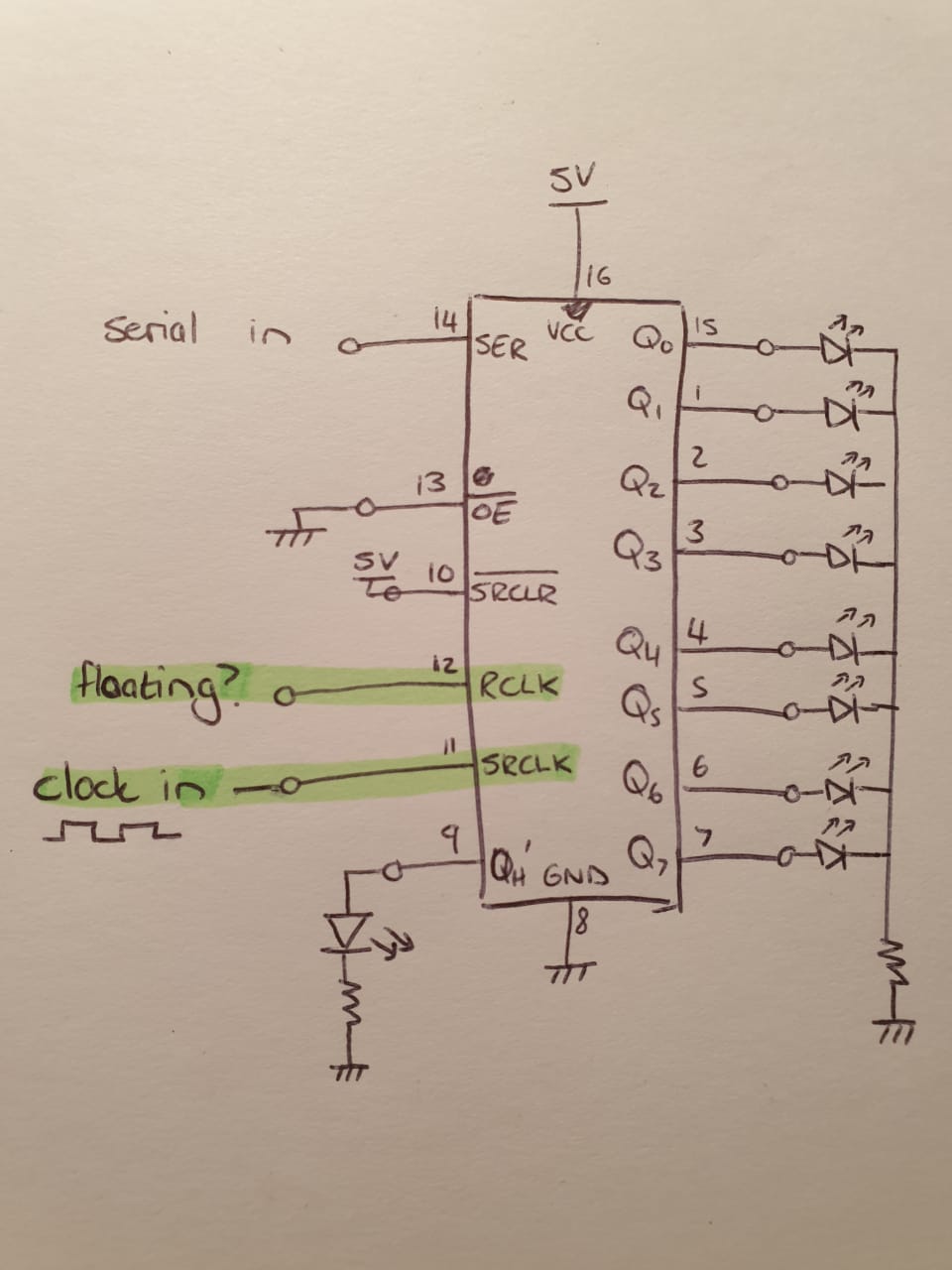
I'm essentially trying to visualise the shifting of the bits with the clock constantly running, and varying the serial input. I want to connect a LED to each output pin, and then connect my input clock (555 timer) to the latching pin (RCLK) and serial clock (SRCLK). As far as I understand the output LEDs should then show the state of the shift register, but delayed by one clock cycle, as mentioned in this datasheet:
If both clocks are connected together the input shift register is always one clock cycle ahead of the output register.
What is not working?
Connected the clocks together makes the shifting stop. Nothing shifts through. Not even in the shift registers, as I connected a LED to QH', and it never lights up.
The funny thing is that I could get it to work by unplugging the RCLKpin and letting it float. Then everything works perfectly, and I see my LEDs shifting. This is strange, as a change of state for RCLK is required for latching.
It even works if I place a switch on RCLK. Then I can see the latching only happening at the up and downward edges, as I expect.
But with the RCLKfloating shows the shifting bits perfectly.
My question:
- Am I understanding how the 74HC595 chip works correctly? Is this intended behaviour?
- Does the two input clocks need to be out of phase, as in the timing diagrams?
- Could it just be EMI? It's built on a breadboard, but I put decoupling caps everywhere. Also, the speed I use never more than 2Hz, so I can't imagine that being the problem.
My setup:
My circuit is built on a breadboard, with the following schematic:


Qnoutputs only show what the storage register stores. And the storage register can only receive new values if the clockRCLKhas an upward flank. So, leaving 'RCLK' floating should not update 'Qn'. :) \$\endgroup\$