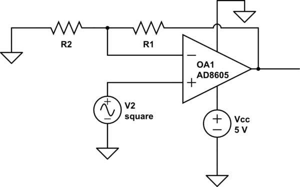
About protecting the opamp:
This one is not internally protected against shorts, so you should put a resistor in series with the output. Tune the resistor value so the maximum current and dissipation in the opamp (and also the resistor) is not exceeded in case of short.
The possible reason for a short between +Vcc and the output could be that something(a loose wire, metal shavings, etc.) physically connects the two OpAmp legs, that there is a break between the tracks on the pcb, or anything else, really. For safety considerations I'm supposed to assume a short occurs, no matter how it actually happens.
If that happens, then it can happen anywhere on your PCB, for example on the component that controls the laser, turning it on permanently.
A circuit on a PCB cannot protect itself against random pins being shorted, unless it is dipped in tamper-proof resin. But then, it cannot protect itself against random component failures either. If someone drops the device on the floor and a heavy component falls off the board, or your capacitors crack, or the PCB cracks, it's probably not going to display a helpful error message, except maybe smoke signals.
So, unless the output of this opamp goes through a connector or something that is much more exposed to short circuits than the PCB itself, it is pointless to protect it.
However a circuit can protect itself against expected failures. For example, in an audio amplifier, if an output transistors blows and welds itself short, the output will be the power supply voltage, with enough current to melt your loudspeakers. So you can have a separate output DC detector circuit and a relay that disconnects the output. This is possible because the most likely (and expensive) source of failure and lawsuits is expected and known.
In your case, if you want proper safety, the safety mechanism should be something like a dead man's switch that would protect against many more failure mechanisms.
For example, put a simple resettable monostable on the laser driver, that the microcontroller has to reset every couple of milliseconds. That way, if the firmware has a bug, or gets stuck in an infinite loop, the laser will turn off. Note firmware bugs are much more likely than hardware bugs.
Then, in your firmware, validate your inputs. This can also be done in analog. For example, if you expect the normal output voltage of your opamp to be 0...4.5V, but you expect 5V in case something fails, like a sensor fails, or the laser driver transistor burning and welding itself short, then an analog comparator can turn off the power supply, for example. If a vital safety mechanism depends on a sensor, it should make sure the sensor is operating correctly, and at least do the right thing if the sensor fails open or short.

