14
\$\begingroup\$

In this article at eetimes.com they show the signal chain for measuring an ECG.

enter image description here

The raw signal of an ECG contains noise and offsets at least a magnitude larger than the real signal. (Some few mV ECG, several tens of mV from power line noise and electrode offset and up to several hundred mV baseline wander due movement of the breast.)

This would intuitively make me do the filtering of the signal in front of the amplifiers, to avoid amplification of the unwanted signal components. In this article however they do the signal filtering after the input amplifier, the high frequency noise removal even after the second amplifier.

I can not really think of a reason why they would do this. The only thing coming to mind is the very high impedance of the signal source, but the filtering would not affect the signal source, because that frequency range would obviously be in the passband.

Am I missing some important reason why you would do the signal conditioning in this order?

\$\endgroup\$
1
  • \$\begingroup\$ That's a pretty good article. \$\endgroup\$ Commented May 16, 2019 at 14:26

4 Answers 4

25
\$\begingroup\$

Am I missing some important reason why you would do the signal conditioning in this order?

Yes you are...

The front-end differential amplifier will be chosen such that it has a common-mode rejection level of many tens of dB, quite possibly in the region of 80 dB.

This diff amp converts a differential signal into a single-ended signal and any common-mode interference will be largely ignored.

If you were to put filters on both legs of the diff amp, to avoid a balance mismatch you would have to choose components (such as capacitors and resistors) that were matched to at least an equivalent level of -80 dB.

You could regard 1% capacitors as having potentially a difference in value of 2% and that, in dB terms could be regarded as -20 log(50) = -34 dB. In other words, you would never get decent differential common-mode performance with filters on each leg before the diff-amplifier.

\$\endgroup\$
4
  • 1
    \$\begingroup\$ Could it be possible that the differential noise is great enough to warrant filtering before the amplifier despite a reduction in CMRR? \$\endgroup\$
    – DavidG25
    Commented May 15, 2019 at 15:25
  • 2
    \$\begingroup\$ Can happen, but would need a DM component much greater then a few hundred mV (100mV gives just half a volt at the output of that amplifier). Another reason to amplify early is that you make the rest of the systems noise FAR less of a problem by applying 14dB of gain in the front end. Now in practise, reality is messy and there will likely be filters before the diff amp, but they will typically be way outside the band of interest so that small tolerances have minimal effect. These exist to keep things like radio transmissions out of the electronics. \$\endgroup\$
    – Dan Mills
    Commented May 15, 2019 at 15:41
  • 1
    \$\begingroup\$ @DanMills: +1 for your last point, though that could be further extended by observing that a cap between the two inputs of the amplifier will supply some low-pass filtering without creating any differential noise, but wouldn't usually be viewed as a "filter" per say in a block diagram. \$\endgroup\$
    – supercat
    Commented May 15, 2019 at 15:52
  • 1
    \$\begingroup\$ @supercat Indeed, and you can take it a step further and split that cap into two in series, then place a SMALL valued one from the junction to chassis ground. The mismatch of the two larger series caps is attenuated because most of the CM voltage in the band of interest is dropped across the small cap to ground while at RF the big series caps are negligible impedances and the cap to ground shunts the RF current. \$\endgroup\$
    – Dan Mills
    Commented May 15, 2019 at 16:15
9
\$\begingroup\$

Andy and Nick offered great answers. Let me try to beef them up just a little.

First, the math says that amplifying then filtering is equivalent to filtering then amplifying. This, of course, applies to the ideal situation, so lets discuss the non-idealities.

The BIG one here, IMO, is saturation. If the noise is so big that it saturates your amplifier, all bets are off. You lose signal. Does this bother us here?? Not really. We usually leave the gain of that InAmp stage low enough to deal with 100mV or so of DC electrode offset, so gain is modest and we're unlikely to saturate.

Next concern involving non-idealities, as already mentioned, is Common Mode noise and CMRR. We want the CMRR in the pass band to be excellent. If we hurt the CMRR in the pass band, we decrease SNR. I'm not totally with Nick on the prefiltering in the kHz range, but I usually follow manufacturer guidelines for RF filtering, and maybe even go a decade in frequency below their recommendations. When I build these filters, I often use X2Y caps to try to keep the caps well-matched.

Lastly, let's think about the signal path all the way to the signal in the body. The impedance of the electrode/skin interface will always vary, and every design needs to take that into account. Because of the tremendous input impedance of today's InAmps, this isn't quite as big a deal as it used to be. In fact, to meet NFPA99 hospital safety standards (when I know I have to bring a device through clinical engineering for inspection) I often put a big honking resistor on each electrode lead to guarantee compliance (<10 microamps)given a failure of Rail voltage at the amp inputs. I match those resistors well, but it probably doesn't make as much difference as I like to think it does, especially given mismatch at the electrode, so to some extent, we're kidding ourselves to make believe that just because we don't throw a filter in before the amp that the signal paths of all electrode leads are well matched -- they're just well matched enough. Variations here, however, can make nailing the cutoff frequency of a filter we choose to put here a bit iffy.

Throw Driven-Leg into the mix, and you're probably about 20dB better. InAmps aren't what they were in John Webster's day. We have inexpensive units with impedances that he could only dream about.

The way I approach such issues is to get my differential signal converted to single-ended as soon as I possibly can, treating as gingerly as I can get away with right up until the Instrumentation Amp with modest gain, and after that, I do whatever I want. With good part selection, you can really get microvolt-level noise with millivolt-level signals.

As a last point, Nick's point about ESD protection is a good one. For my stuff, I don't particularly care, but have you ever wondered how clinical ECG units don't just pop when a patient is defibrillated? Thousands of volts presented to the inputs, and a well-designed unit just laughs and goes about it's business.

\$\endgroup\$
8
\$\begingroup\$

I'll second @Andy's answer, and I'd like to add one thing.

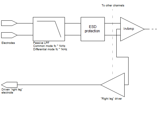
A passive low-pass filter between the electrodes and the InAmp is called for. I put the cutoff frequency somewhere in the kHz region.

block diagram with low-pass filter between electrodes and instrumentation amplifier

InAmps have a great CMRR at low frequencies, but the CMRR degrades at higher frequencies (above 3kHz-10kHz depending on the chip). Rectification at high frequencies is another concern for InAmps. A high frequency signal may get rectified by InAmp's input stage and then appear as a DC offset.
(More in this app note: Analog Devices MT-070. In-Amp Input RFI Protection.)

Since the EKG signal is low so the high frequency can be filtered out even with somewhat mismatched passive components.

\$\endgroup\$
4
  • 2
    \$\begingroup\$ High frequencies don't need to be filtered as common mode, because they can be filtered by lowpass AFTER the amplifier. You don't want passives in front of the amplifier on any small signal system, and especially on an ECG you want all the measurement electrodes to be connected to "infinite" input impedance FET stages incapable of passing current through the body. The RL drive slowly equalizes your circuit ground and body ground, you do NOT want to form a circuit with current flowing out RL drive and into a measurement channel. \$\endgroup\$
    – Ben Voigt
    Commented May 16, 2019 at 2:37
  • 1
    \$\begingroup\$ @Ben High frequency common mode should be filtered out before the InAmp. InAmps reject common mode at low frequencies well. Unfortunately, InAmps have problems with high frequency common mode (above 10kHz, although this varies from one model of InAmp to another). CMRR is frequency-dependent, and it goes down at higher frequencies. [Just to keep to the subject. I view this mainly as a matter of protecting InAmp against EMI. If we want to consider patient safety aspects, I'd be happy to do that too.] \$\endgroup\$ Commented May 16, 2019 at 3:10
  • \$\begingroup\$ You don't need CMRR at frequencies higher than the signal band. If they pass through the in-amp, it doesn't matter, because the following bandpass filters them out. What you don't want are any noise sources ahead of the first amplifier. \$\endgroup\$
    – Ben Voigt
    Commented May 16, 2019 at 3:48
  • 1
    \$\begingroup\$ @Ben In addition to reduced CMRR at high frequency, InAmps also suffer from rectification [non-linear behavior] at high frequency. A high frequency signal may get rectified by InAmp's input stage and then appear as a DC offset at the output. More in this app note: Analog Devices MT-070. In-Amp Input RFI Protection. \$\endgroup\$ Commented May 16, 2019 at 4:29
7
\$\begingroup\$

The only filtering you ever do before the first amplifier is that related to shape of antenna/waveguide. And that only applies to microwave and higher frequencies.

Conventional passive filters add noise -- you want the signal to be as large compared to that added noise as possible. Even if it means you are also amplifying interfering signals, you aren't changing the ratio of signal to in-band interfering signals, so you can filter interference just as effectively after amplification as before. But you cannot amplify as effectively after filtering, because you're already mixed in the filter's noise.

Then you'll frequently amplify again after filtering, since now the full dynamic range can be applied to the frequencies of interest. But this is in addition to the pre-amplification, not instead.

\$\endgroup\$

Your Answer

By clicking “Post Your Answer”, you agree to our terms of service and acknowledge you have read our privacy policy.

Not the answer you're looking for? Browse other questions tagged or ask your own question.