0
\$\begingroup\$

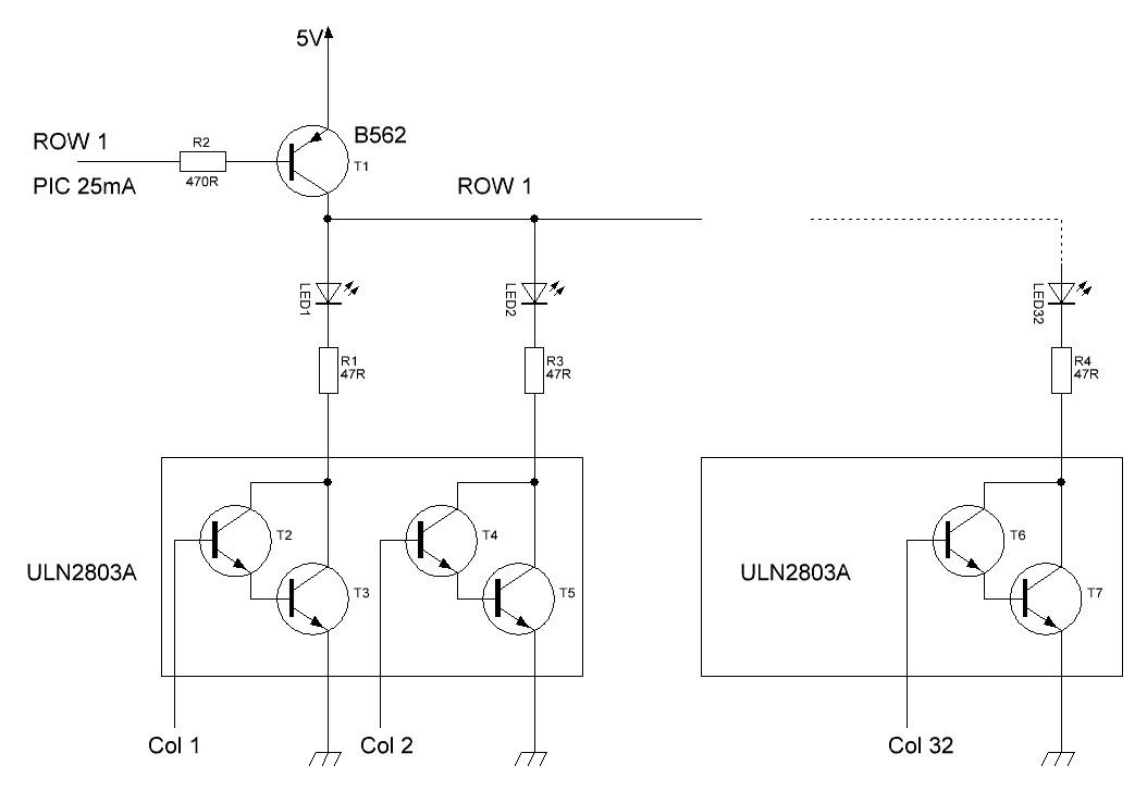
The schematic shows one row of my 16(row)x32(Col) LED matrix. Each row has 32 LEDs. I'm Scanning rows @ 1/16th rate.I'm using a PIC micro controller. I use 3V LEDs. The problem is LEDs are dim.

How to overcome my problem? I'm about to draw my new PCB, so changes are welcome. enter image description here

\$\endgroup\$
3
  • 1
    \$\begingroup\$ You mention scanning rate but what's the scanning frequency? \$\endgroup\$
    – TonyM
    Commented May 17, 2019 at 18:09
  • \$\begingroup\$ Scanning rate is 104Hz. \$\endgroup\$
    – Joseph143
    Commented May 28, 2019 at 0:20
  • \$\begingroup\$ So, just to be certain, each LED is lit for 9.6 ms per second. \$\endgroup\$
    – TonyM
    Commented May 29, 2019 at 9:54

1 Answer 1

7
\$\begingroup\$

My guess would be that the Vce(sat) drops of both the ULN2803, the high-side transistor and the voltage drop on the current-limiting resistors could easily add up to roughly 2V or more, not leaving much room for the 3V LEDs with a 5V power supply.

Try using NPNs directly instead of the ULN2803's to give you more headroom, or change your current-limiting resistor to a lower value to account for the lower voltage available.

Another option would be to simply use a higher voltage for the LED drive to give you more room, although you'd likely have to drive the high sides differently (perhaps using some of the leftover ULN's to drive the PNP bases to ground, if you have some left over.)

Edit: You may also want to increase the LED current anyhow to combat the inherent 1/16 duty cycle in your design.
\$\endgroup\$
1
  • \$\begingroup\$ OK, Thank you very much.I understood.I think better is to increase supply voltage to the LEDs.I'll give a try. \$\endgroup\$
    – Joseph143
    Commented May 28, 2019 at 0:35

Your Answer

By clicking “Post Your Answer”, you agree to our terms of service and acknowledge you have read our privacy policy.

Not the answer you're looking for? Browse other questions tagged or ask your own question.