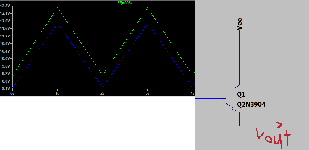
Input voltage triangular wave signal with 12.7Vmax and 9.1Vmin passing thru a NPN BJT, assuming if the forward voltage of the BJT is 0.7V then why is the output Vmax is not 12.0V but way lower like 11..V. Here the graph and the part of the schematic diagram. Vout is in blue and Vin is in green. Any idea on why this happened and how to make it have a gain of 1 for the voltage?
\$\begingroup\$
\$\endgroup\$
4
-
1\$\begingroup\$ It does appear to have a gain of 1. Why do you think it's not? And what is loading the emitter of Q1? \$\endgroup\$– jonkCommented May 21, 2019 at 17:44
-
\$\begingroup\$ There will always be a CE drop of about 0.2V or more. See fig 16 onsemi.com/pub/Collateral/2N3903-D.PDF The voltage drop of 0.7V is between base and emitter. This is why the NPN is usually operated in sink mode (emitter to ground, load between Vcc and collector) \$\endgroup\$– IndraneelCommented May 21, 2019 at 17:45
-
\$\begingroup\$ @jonk HMM I always thought a gain of 1 means the Vin and Vout should be the same, and it is loading to a led module \$\endgroup\$– Gary KhawCommented May 21, 2019 at 18:02
-
\$\begingroup\$ @GaryKhaw, gain of one means that a 1 V change in the input produces a 1 V change in the output. It doesn't imply 0 difference between the two voltages. \$\endgroup\$– The PhotonCommented May 21, 2019 at 18:03
Add a comment
|
1 Answer
\$\begingroup\$
\$\endgroup\$
Vbe voltage of 0.7V is not a hard law, more like a good-enough simple rule-of-thumb kind of approximation. Even the transistor datasheet says a range for Vbe.
The gain is 1, you just have a voltage bias offset of Vbe.

