i have a strange problem, maybe this post will be long, but i try to give all the details:
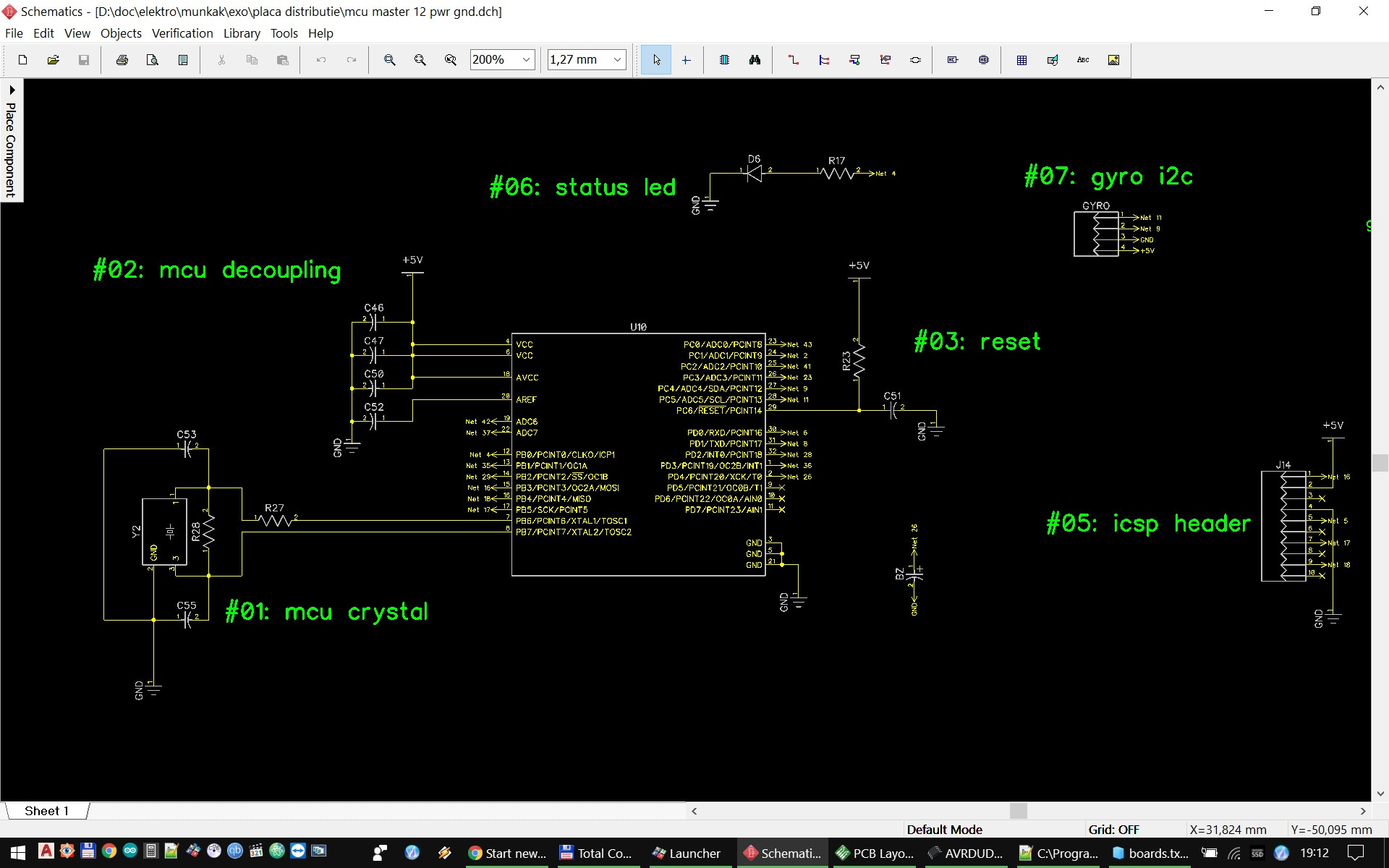
i’ve designed a pcb with smd components, around the atmega328pb mcu. it uses an external 16mhz clock and has all the needed decoupling caps, voltage regulator, etc. i’m sure that the design should work, because i already used the same arrangement in other projects.
i have ordered the parts from tme.eu, the exact model of the mcu is ATMEGA328PB-AN. these are smd parts, so, before programming, you have to solder it in place. i have some experience with atmel mcu, already used several types, like 328, 2560, attiny, etc. for programing i use usbasp device from ali. (https://www.aliexpress.com/item/FREE-SHIPPING-1LOT-New-USBASP-USBISP-AVR-Programmer-USB-ATMEGA8-ATMEGA128-Support-Win7-64K/2003972227.html)
so far, i have used this device without problem. however, with these new chips, i can’t manage to work:
first, i’ve tried the simple arduino ide method, selecting: tools > arduino nano > atmega328p tools > programmer > usbasp tools > burn bootloader
in the first instance, the upload didn’t worked, because of the different chip id (between atmel328p and 328pb). so i edited the c:\Program Files (x86)\Arduino\hardware\tools\avr\etc\ avrdude.conf file, line 8797, to signature = 0x1e 0x95 0x16;
this way it apparently uploaded the bootloader, however, the mcu gets bricked, no longer answers to any code uploading attempt nor bootloader uploading attempt (tried with usbasp, another arduino via isp, etc)
so, i’ve desoldered the mcu, and soldered another brand new one. this time i’ve tried the avrdudess v2.8 app. based on this article: http://www.electronics-lab.com/burning-the-bootloader-on-atmega328-using-usbasp-programmer/
here the app detected the usbasp, detected the correct mcu model. i have done everything exactly as in the article, double checked everything. hitted the program! button, and got this output. as you can see, it apparently failed to write the extended fuse correctly, and probably this is bricking the mcu. i’ve checked with the fuse bit calculator, and for the extended fuse 0xf5 is not an option…
now it no longer can read the fuse bits, no longer can program the mcu, nothing works 🙁 bricked 2 mcu so far. just to be sure, i’ve checked the 16mhz clock signal with a scope, it works, got the nice sine wave.
also, desoldered a working mcu from an arduino nano, and soldered into my pcb, it works ok, i can upload sketch via the usbasp.
Checking for updates…
You have the latest version 🙂
Detected 1e9516 = ATmega328PB
Reading fuses…
SUCCESS: Read low fuse
SUCCESS: Read high fuse
SUCCESS: Read extended fuse
Reading lock bits…
SUCCESS: Read lock bits
optiboot_atmega328.hex: 502 / 32,768 Bytes (1.53%)
~ ~ ~ ~ ~ ~ ~ ~ ~ ~ ~ ~ ~ ~ ~ ~
avrdude.exe: set SCK frequency to 1500000 Hz
avrdude.exe: warning: cannot set sck period. please check for usbasp firmware update.
avrdude.exe: AVR device initialized and ready to accept instructions
Reading | ################################################## | 100% 0.00s
avrdude.exe: Device signature = 0x1e9516 (probably m328pb)
avrdude.exe: NOTE: “flash” memory has been specified, an erase cycle will be performed
To disable this feature, specify the -D option.
avrdude.exe: erasing chip
avrdude.exe: set SCK frequency to 1500000 Hz
avrdude.exe: warning: cannot set sck period. please check for usbasp firmware update.
avrdude.exe: reading input file “C:\Program Files (x86)\Arduino\hardware\arduino\avr\bootloaders\optiboot\optiboot_atmega328.hex”
avrdude.exe: input file C:\Program Files (x86)\Arduino\hardware\arduino\avr\bootloaders\optiboot\optiboot_atmega328.hex auto detected as Intel Hex
avrdude.exe: writing flash (32768 bytes):
Writing | ################################################## | 100% 0.00s
avrdude.exe: 32768 bytes of flash written
avrdude.exe: verifying flash memory against C:\Program Files (x86)\Arduino\hardware\arduino\avr\bootloaders\optiboot\optiboot_atmega328.hex:
avrdude.exe: load data flash data from input file C:\Program Files (x86)\Arduino\hardware\arduino\avr\bootloaders\optiboot\optiboot_atmega328.hex:
avrdude.exe: input file C:\Program Files (x86)\Arduino\hardware\arduino\avr\bootloaders\optiboot\optiboot_atmega328.hex auto detected as Intel Hex
avrdude.exe: input file C:\Program Files (x86)\Arduino\hardware\arduino\avr\bootloaders\optiboot\optiboot_atmega328.hex contains 32768 bytes
avrdude.exe: reading on-chip flash data:
Reading | ################################################## | 100% -0.00s
avrdude.exe: verifying …
avrdude.exe: 32768 bytes of flash verified
avrdude.exe: reading input file “0xFF”
avrdude.exe: writing lfuse (1 bytes):
Writing | ################################################## | 100% 0.00s
avrdude.exe: 1 bytes of lfuse written
avrdude.exe: verifying lfuse memory against 0xFF:
avrdude.exe: load data lfuse data from input file 0xFF:
avrdude.exe: input file 0xFF contains 1 bytes
avrdude.exe: reading on-chip lfuse data:
Reading | ################################################## | 100% 0.00s
avrdude.exe: verifying …
avrdude.exe: 1 bytes of lfuse verified
avrdude.exe: reading input file “0xDE”
avrdude.exe: writing hfuse (1 bytes):
Writing | ################################################## | 100% 0.01s
avrdude.exe: 1 bytes of hfuse written
avrdude.exe: verifying hfuse memory against 0xDE:
avrdude.exe: load data hfuse data from input file 0xDE:
avrdude.exe: input file 0xDE contains 1 bytes
avrdude.exe: reading on-chip hfuse data:
Reading | ################################################## | 100% 0.00s
avrdude.exe: verifying …
avrdude.exe: 1 bytes of hfuse verified
avrdude.exe: reading input file “0x05”
avrdude.exe: writing efuse (1 bytes):
Writing | ***failed;
################################################## | 100% 0.03s
avrdude.exe: 1 bytes of efuse written
avrdude.exe: verifying efuse memory against 0x05:
avrdude.exe: load data efuse data from input file 0x05:
avrdude.exe: input file 0x05 contains 1 bytes
avrdude.exe: reading on-chip efuse data:
Reading | ################################################## | 100% 0.00s
avrdude.exe: verifying …
avrdude.exe: verification error, first mismatch at byte 0x0000
0xf5 != 0x05
avrdude.exe: verification error; content mismatch
avrdude.exe done. Thank you.
Reading fuses…
WARNING: Unable to read fuses/lock bits
avrdude.exe: set SCK frequency to 1500000 Hz
avrdude.exe: warning: cannot set sck period. please check for usbasp firmware update.
avrdude.exe: error: program enable: target doesn’t answer. 1
avrdude.exe: initialization failed, rc=-1
Double check connections and try again, or use -F to override
this check.
avrdude.exe done. Thank you.
best regards, thanks!

