0
\$\begingroup\$

I can't understand some stuff about op-amps. Here is my list of doubts:

  1. If an op-amp amplify the difference between the V+ and the V-, how can it work if for the principle of virtual ground V+ = V-, and so if V+ = V- there aren't difference to amplify.

  2. Considering this circuit as the ideal one of the op-amp, why V+ = V- ? Why does the principle of virtual ground exist? Why is the voltage on V+ is equal to the one in V- ?

    enter image description here

    Is correct to say that all the Vin applied on this equivalent circuit will fall on the Ri?

  3. Take a look at this circuit, my teacher says that I1 is equal to I2, but I can't understand why:

    enter image description here

    If the two resistor have respectively a knot to mass, the only condition when I1 = I2 is when Vin = Vo and when R1 = R2

  4. The I1 and the I2 that will go to the point of the virtual ground (the point marked on this photo), where will they go at the end? Will they go to the physical ground?

    enter image description here

\$\endgroup\$
5
  • 2
    \$\begingroup\$ Possible duplicate of Ideal OP-AMP - why isn't output voltage zero? \$\endgroup\$
    – The Photon
    Commented May 30, 2019 at 17:54
  • \$\begingroup\$ Also analyzing op amp circuit \$\endgroup\$
    – The Photon
    Commented May 30, 2019 at 17:55
  • \$\begingroup\$ You are missing minus signs in your circuits. You have an inverting op-amp circuits, so Vout = -Vin. Then I2 flows away from the - input towards the output, so the input current flows to the right through both Rin and Rf. \$\endgroup\$ Commented May 30, 2019 at 19:23
  • \$\begingroup\$ Possible duplicate of electronics.stackexchange.com/q/465236/68782 \$\endgroup\$
    – Roland
    Commented Apr 22, 2021 at 12:32
  • \$\begingroup\$ I1 + I2 = 0 since opamp input current is appr. zero. Hence, I1 = minus I2. Kirchhoff law on currents. Electronics 101. It makes no difference if V+ is not zero. Then I1 + I2 is still zero, just Vout will be different. The difference is V+, amplified with the ratio of both R's. \$\endgroup\$
    – Roland
    Commented Apr 22, 2021 at 12:41

3 Answers 3

11
\$\begingroup\$

If an op-amp amplify the difference between the V+ and the V-, how can it work if for the principle of virtual ground V+ = V-, and so if V+ = V- there aren't difference to amplify.

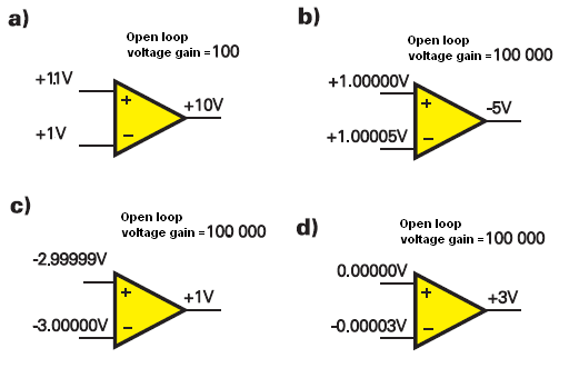
You are right, in real life, the op-amp alone (without any feedback loop) is nothing more than a differential amplifier. The output voltage is the difference between the \$+\$ and \$-\$ inputs multiplied by the open-loop gain (Aol):

\$ V_{OUT} = (V_+ − V_−)*A_{OL} \$
enter image description here

Also, you must remember that the op-amp open loop gain is very large; therefore very small change between the input voltage will cause a large change at the output (Fig. b, c, and d).

The voltage difference at the input must be equal to:

\$V_+ - V_− = \frac{Vout}{A_{OL}} = \frac{3V}{100\: 000} = 30\mu V\$ (Fig. d)

As you can see this difference is indeed very small. Hence, we can say without much of an error that \$V_+ \approx V_−\$ when op-amp is working in a linear region (negative feedback applied around the op-amp) and when the open loop gain is very high.

Additionally in circuit theory we analyze the circuit assuming that we have an ideal opamp. And one of the properties of an ideal op-amp is that it has infinity large open loop gain. Try to think about it for a while. And I hope that now you see why \$V_+ = V_−\$ is true for the ideal op-amp case (infinite open-loop gain).

Back to the basic

When the voltage at the input "+" (non-inverting) rises, the output voltage is also increasing. Increase voltage at "-" input (inverting input) causes, decrease the output voltage. Decrease voltage at input "-" increases the output voltage.

enter image description here

Now try to analyze this circuit:

enter image description here

In this circuit has negative feedback applied by the R2 resistor.

Now let us understand how the negative feedback returned through R2 affects the amplifier operation. To begin our discussion, let us momentarily freeze the input signal as it passes through 0 volts. At this instant, the op amp has no input voltage (i.e., VD = 0 = voltage between the (+) and (-) input terminals (VD)). It is this differential input voltage that is amplified by the gain of the op amp to become the output voltage. In this case, the output voltage will be 0. Now suppose the output voltage tried to drift in a positive direction. Can you see that this positive change would be felt through R2 and would cause the inverting pin (-) of the op amp to become slightly positive Since essentially no current flows in or out of the op amp input and the (+) input of the op amp is at ground potential. This causes VD to be greater than 0 with the (-) terminal being the most positive. When VD is amplified by the op amp it appears in the output as a negative voltage (inverting amplifier action). This forces the output, which had initially tried to drift in a positive direction, to return to its 0 state. A similar, but opposite, action would occur if the output tried to drift in the negative direction. Thus, as long as the input is held at 0 volts, the output is forced to stay at 0 volts.

Now suppose we allow the input signal to rise to at +2 volt instantaneous level and freeze it for purposes of the following discussion. With +2 volts applied to R1 and 0V at the output of the op amp, the voltage divider made up of R2 and R1 will have two volts across it. Since the (-) terminal of the op amp does not draw any significant current, the voltage divider is essentially unloaded. We can see, even without calculating values, that the (-) input will now be positive. Its value will be somewhat less than 2 volts because of the voltage divider action, but it will definitely be positive. The op amp will now amplify this voltage (VD) to produce a negative-going output. As the output starts increasing in the negative direction, the voltage divider now has a positive voltage (+2 volts) on one end and a negative voltage (increasing output) on the other end. Therefore the (-) input may still be positive, but it will be decreasing as the output gets more negative. If the output goes sufficiently negative, then the (-) pin (VD) will become negative. If, however, this pin ever becomes negative then the voltage would be amplified and appear at the output as a positive going signal. So, you see, for a given instantaneous voltage at the input, the output will quickly ramp up or down until the output voltage is large enough to cause VD to return to its near-0 state. All of this action happens nearly instantaneously so that the output appears to be immediately affected by changes at the input.

And the situation in the circuit when the open loop gain has a finite value.

enter image description here

\$\endgroup\$
4
  • \$\begingroup\$ Could you please provide links or citations for the images that you used? \$\endgroup\$ Commented May 30, 2019 at 19:45
  • \$\begingroup\$ @ElliotAlderson here you have elportal.pl/pdf/k01/46_08.pdf and I also use MSpain to edit the images. \$\endgroup\$
    – G36
    Commented May 31, 2019 at 20:09
  • \$\begingroup\$ @G36, I enjoyed reading your explanation... and I share it. I just want to make some small remarks. Yes, this is actually the way to explain the circuit - by thinking of an op-amp not of as an instantaneous device (amplifier) but of as a slow acting device that analyzes the difference and decides in which direction to change its output voltage (integrator). But I have noticed that students have a hard time accepting the idea of thinking of an amplifier as of an integrator... \$\endgroup\$ Commented Feb 15, 2021 at 21:26
  • \$\begingroup\$ Another remark: The negative feedback is introduced not only by R2 but by both R1 and R2 (you know very well the voltage cannot be attenuated only by one resistor). Basically, the two resistors in series form a passive summing circuit with weighted inputs that sums (subtracts) the input and output voltage. I agree with you that in the beginning, due to the "slow acting" op-amp, its output voltage does not "move"... and this network is grounded from the right side... thus acting as a voltage divider driven by the left side... But then it is driven by both sides... \$\endgroup\$ Commented Feb 15, 2021 at 21:33
0
\$\begingroup\$

If an OP-AMP amplify the difference between the V+ and the V-, how can it work if for the principle of virtual masses V+=V-, and so if V+=V- there aren't difference to amplify.

The principle of virtual nodes (setting one equal to the other) only applies if there is negative feedback. If there are not feedback resistors, it won't work. If there isn't feedback, then the open loop gain equation Vout = Aol*(V+-V-) must be used to determine the value of the output.

Considering this circuit as the ideal one of the OP-AMP, why V+=V- ?(Why the principle of virtual masses exist)Why the voltage on V+ is equal to the one in V- ?

If the op amp has negative feedback, it will make every effort to drive the terminals to be the same value, this is why we can consider them equal.

Take a look at this circuit, my teacher says that I1 is equal to I2, but I can't understand why:enter image description here

In an ideal opamp, current cannot flow into V+ or V- they have infinite resistance/impedance. So the current can only go through the resistors. In the real world, the current is very small, usually nA or pA into V+ and V-, and the input impedance is very very high, well over the mega ohm range.

The I1 and the I2 that will go to the point of the virtual mass (The point marked on this photo) where were they go at the end? Will they go to the phisical ground?

The problem is the convention of your currents, that is causing confusion. In your diagram with the way you have the arrows drawn, I2 = -I1. In an ideal op amp the current cannot go into the V+ or V- port.

\$\endgroup\$
0
\$\begingroup\$

1) Because of feedback resistors. The output swings to such a voltage (if possible) that difference between V- and V+ is zero.

2) The image does not show feedback, so the op-amp output can't change V+ or V-. The image just shows that an ideal opamp has input pins, almost infinite input resistance, and output voltage is input voltage times almost infinite gain.

3) Because current does not flow into op-amp V-, all current that flows through R1 must also flow through R2, there is no other path for the current. And as it is an inverting op-amp, output must be negative to get zero volts on V-, therefore, Vo = -Vin.

4) The current directions are same, not opposite. So current from input goes to op-amp output, via both resistors.

\$\endgroup\$
4
  • \$\begingroup\$ Feedback does not force the difference between V- and V+ to zero. It forces it to a value that is Vout/gain. E.g. If Vout = 3 V and the gain is 100 then the difference between V- and V+ will be 3/100 = 30 mV. In many practical situations we assume an approximate value of zero. But its not really zero. \$\endgroup\$
    – scorpdaddy
    Commented May 30, 2019 at 18:34
  • \$\begingroup\$ Not all of the current goes from R1 to R2. There is a small amount of leakage current that does go into the op amp. \$\endgroup\$
    – scorpdaddy
    Commented May 30, 2019 at 18:35
  • \$\begingroup\$ @scorpdaddy, with ideal op-amps, input voltage difference is zero and there will be no leakage current into op-amp. Non-ideal op amps do have leakage, and offset voltages, but your calculations about difference between inputs does not seem to take account the non-ideal open-loop gain of about 100000 anywhere, only the feedback gain. That can't be right. \$\endgroup\$
    – Justme
    Commented May 30, 2019 at 18:42
  • \$\begingroup\$ Use what ever gain is appropriate for the device. The output voltage is gain times the input voltage difference. So the reverse is also true: the voltage difference is the output voltage / gain. In other words, some finite, non-zero value. \$\endgroup\$
    – scorpdaddy
    Commented May 30, 2019 at 19:01

Not the answer you're looking for? Browse other questions tagged or ask your own question.