I'm looking to design a soft-start precharge circuit for starting up circuits with substantial input capacitance (~1.5J @ 24V). The main requirements are:
- 24-60V compatible
- Constant current pre-charge
- Enable/disable via low-current switch
- Protection against inrush if accidentally connected with switch enabled
- No sharp current/voltage deltas during precharge or transition
- LED indicator to show when capacitors are charged
- Connection order doesn't matter
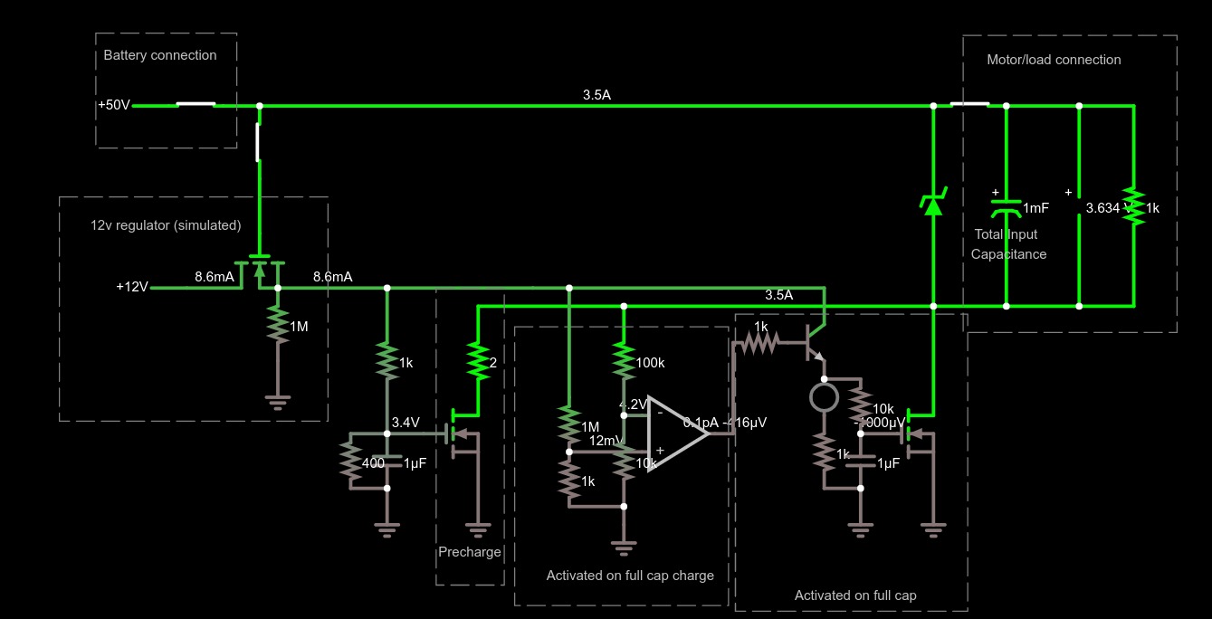
This is the circuit I've come up with (Falstad link):
Note that the switch would control the 12v regulator, but I can't find one in Falstad so I had to simulate one.
The theory of operation is that once the battery and downstream load is connected and the 12v regulator is enabled via the switch, the precharge power MOSFET gate begins to charge. Once it hits the threshold and maximizes in the non-linear region (limiting current, in this case to ~3.5A), current begins to flow through the downstream capacitors to a 2Ohm power resistor. As it charges, an op-amp measures the voltage on the negative side of the downstream circuit. Once the difference in voltage falls below the voltage on the non-inverting amp input, the op amp turns on, delivering 12v to the final stage. The transistor is switched on, causing the gate of the final power MOSFET to begin charging. Once the gate threshold is hit, it turns on, bypassing the power resistor and enabling full current to flow.
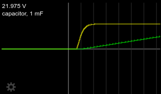
AFAICT it works, at least in simulation. The current slowly increases up to a constant level, and voltage across the capacitor begins charging linearly...
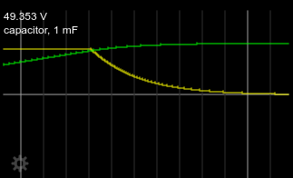
...the current slows down as the capacitor fills up...
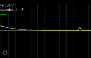
...and the final transition to the power MOSFET is a smooth, small "bump" in current:
Charge times:
- 1mF@24V: 19ms
- 10mF@24V: 140ms
- 1mF@50V: 28ms
- 10mF@50V: 240ms
Does this seem reasonable? Any obvious mistakes/concerns? The only point I don't think I have solved is #7 above. If the switch is off, the battery/load connection order doesn't matter. If the switch is accidentally left on and the load is connected first, followed by the battery, everything works. However, if the switch is on and the battery is connected first, the op-amp thinks the voltage across the capacitor is the full voltage and happily charges the cap in the lower right. That's a problem, since when the load is eventually connected the cap keeps the power MOSFET's gate high and allows hundreds of amps to go through before the cap can drain and the remaining circuity catches up. I figure I can be careful to always connect the battery last, but if possible I'd love to protect against my own absent-mindedness!


