1
\$\begingroup\$

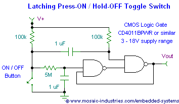
I'm very new at all this and hope you will have patients with me, I'm trying to use this circuit diagram to turn a momentary switch into a latching switch, I though it would be straightforward but alas,

enter image description here

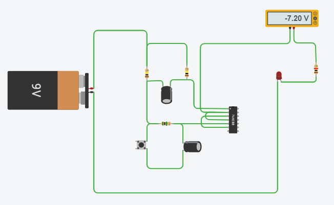
I'm building it in tinkercad.com but cannot figure out where the power source (9V) connects and where the load connects. I'm thinking V+ goes to the Battery pack Positive and Vout to the Negative, but I have no idea where the ground connection should go. The circuit turns on, but there is no switching

enter image description here

Thank you for your time.

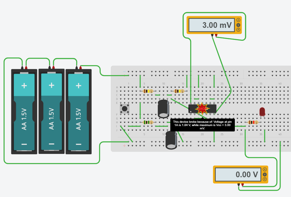
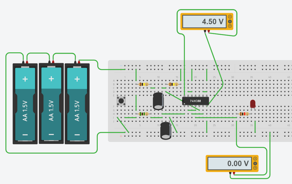
I have now tried to build this on a virtual breadboard, I have lowered the voltage form 9V to 4.5V as the 74HC00 is only rated for 5V. When the button is pushed the chip fails with the following error "Voltage at pin 1A is 1.84 V while max is Vcc=30.mV I'm sure I'm missing something obvious but I really have no idea, hope some one can help me out. enter image description here
enter image description here

\$\endgroup\$
1
  • \$\begingroup\$ Welcome to EE.SE! Minus goes to your ground symbol and plus goes to V+ in your schematic. \$\endgroup\$
    – winny
    Commented Jul 2, 2019 at 7:09

1 Answer 1

1
\$\begingroup\$

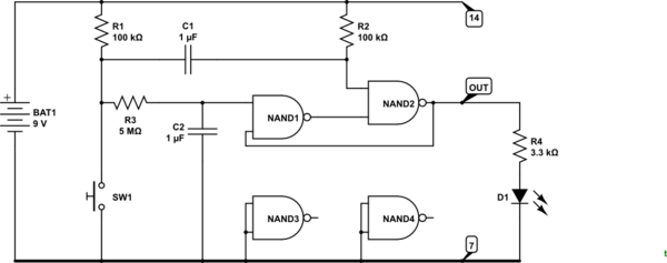
schematic

simulate this circuit – Schematic created using CircuitLab

Figure 1. Redrawn circuit.

I'm thinking V+ goes to the battery pack positive ...

Correct.

... and Vout to the negative, ...

No, VOUT is what drives the load. That's what's driving D1, the LED, in Figure 1.

... but I have no idea where the ground connection should go.

In most circuits with a single supply voltage negative is the "ground" or 0 V or reference rail. I've shown it heavy in Figure 1 which makes it clear.

CMOS inputs should not be left floating so NAND3 and NAND4 have their inputs grounded. They could be connected to V+ if it was easier.

\$\endgroup\$
2
  • \$\begingroup\$ Thank you, it makes a lot ore sense now. I will use CircuitLab tonight and see if I can make it work. One more question related to you diagram, what does the 14 and 7 (top and bottom in the diagram) mean ? \$\endgroup\$
    – Christo
    Commented Jul 2, 2019 at 6:46
  • \$\begingroup\$ The CMOS chip requires power. Pin 14 is connected to positive. Pin 7 is connected to GND. That's not shown on your cartoon diagram so if you didn't connect those then you were doomed. \$\endgroup\$
    – Transistor
    Commented Jul 2, 2019 at 7:58

Your Answer

By clicking “Post Your Answer”, you agree to our terms of service and acknowledge you have read our privacy policy.

Not the answer you're looking for? Browse other questions tagged or ask your own question.