38
\$\begingroup\$

I am new to microcontroller programming. I am using ATmega32-A controller and CodeVisionAVR compiler. I am using the waveform generator(AD9833) to generate a sinewave signal using SPI communication. I am able to generate the sinewave successfully. Now I am passing that signal to the sensor. The sensor output is selected through the multiplexer and sent to the ADC. Now I want read ADC values using SPI communication. I have tried a lot to setup the registers of ADC. Still it is not working. To see SPI communication Code have a look at my previous post ADC registers setup using spi communication. I am using USART(RS232) communication to print values on PC(PuTTY).

Someone advised me to use bit-banging. I am new to that concept. Can any one provide me an example code of bit banging of SPI communication. How to start that procedure? Can any one provide me a good materiel. Do I need any external hardware?

I have written this, including pin connections:

#define ADC_CS PORTB.3
#define MOSI PORTB.5
#define MISO PINB.6
#define SCK PORTB.7

void send_8bit_serial_data(unsigned char data)
{
    int i;  
    ADC_CS=0;
    for (i = 0; i < 8; i++)
    {
        // consider leftmost bit
        // set line high if bit is 1, low if bit is 0
        if (data & 0x80)
            output_high(PORTB.5);
        else
            output_low(PORTB.5);

        // pulse clock to indicate that bit value should be read
        output_low(PORTB.7);
        output_high(PORTB.7);

        // shift byte left so next bit will be leftmost
        data <<= 1;
    }

    // deselect device
    ADC_CS=1;
}
\$\endgroup\$
4
  • 4
    \$\begingroup\$ en.wikipedia.org/wiki/Bit_banging \$\endgroup\$
    – kenny
    Commented Oct 15, 2012 at 14:22
  • \$\begingroup\$ Your code looks okay apart from the clock output low should be before the bit setting and delay. You need a couple of delays to fix the timing (so clock low/high are roughly the same period) Have a look at Steven's code again. If you want to read as well you will need to add the code for that too. \$\endgroup\$
    – Oli Glaser
    Commented Oct 15, 2012 at 14:55
  • \$\begingroup\$ @OliGlaser Can I use directly this code instead of normal SPI Code that to setup registers. \$\endgroup\$
    – verendra
    Commented Oct 15, 2012 at 15:17
  • \$\begingroup\$ @verendra - not sure what you mean by "normal SPI code". If you mean instead of hardware SPI, then the ADC doesn't care how the pulses are generated as long as they agree with the protocol and timing. \$\endgroup\$
    – Oli Glaser
    Commented Oct 15, 2012 at 15:21

2 Answers 2

31
\$\begingroup\$

Bit banging is creating the whole series of pulses in software, instead of relying on a piece of hardware inside the microcontroller.

Many microcontrollers have a hardware SPI, and then all you have to do is write a byte to the output register, and the SPI controller will shift the data out, and at the same time receive data from the slave. You can get an interrupt when the transfer is complete, and then read the received data.

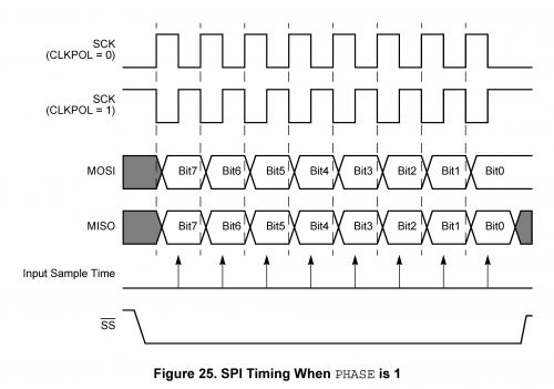
But some microcontrollers don't have the SPI hardware on board and then you have to simulate it by doing everything manually. SPI has a number of different modes, I'll use this pulse diagram as an example:

enter image description here

So while a dedicated SPI controller takes care of all the pulses, data shifting and timing, when bit-banging you have to take every action yourself:

Make Slave Select low  
Short delay
Do 8 times
  Make the SCK (Serial Clock) pin low 
  Make the MOSI (Master-Out-Slave-In) pin high or low depending on bit 7 of the data  
  Add brief delay  
  Make the SCK output high
  Read MISO (Master-In-Slave-Out) pin
  Shift received data left, and shift the bit just read in as bit 0   
  Add brief delay  
  Shift the data byte 1 bit left
Make Slave Select high again  

Bit-banging SPI is relatively simple, the code for bit-banging I2C for instance will be more complex, and you'll need a timer somehow if you want to bit-bang the UART protocol.

\$\endgroup\$
5
  • 2
    \$\begingroup\$ Can you provide a sample c code. \$\endgroup\$
    – verendra
    Commented Oct 15, 2012 at 14:14
  • 2
    \$\begingroup\$ @verendra - I added a pseudocode example, which you should be able to translate easily into C. \$\endgroup\$
    – stevenvh
    Commented Oct 15, 2012 at 14:21
  • \$\begingroup\$ I am succesfully generating Wavefrom using SPI communication. I have problem with reading ADC values using SPI only. I have to use bit banging for both or just only to read ADC values. Can you have a look at my code to send 8 bit , is it write. but I am confusing how to use it. Can I place this code directly instead of my SPI code to setup register. \$\endgroup\$
    – verendra
    Commented Oct 15, 2012 at 14:41
  • \$\begingroup\$ @Steven - the diagram you show is MSB first, so you need to left shift out from 7 and left shift in from 0. I know there is no standard so it can be LSB first, but I think most SPI peripherals do it this way. \$\endgroup\$
    – Oli Glaser
    Commented Oct 15, 2012 at 15:08
  • 2
    \$\begingroup\$ @Oli - good point, I missed that. I'll fix it, thanks for the feedback. The reason there's no standard is that it doesn't matter as long as the number of transferred bits is equal to the shift register length. Recently some microcontrollers (like NXP Cortec-M3) have a variable length shift register, and then direction may matter. IIRC in the AVR you can select MSB first or LSB first. \$\endgroup\$
    – stevenvh
    Commented Oct 15, 2012 at 15:14
12
\$\begingroup\$

Bit-banging refers to the concept of having the signals which go out of or come into a device be generated/sampled by software rather than hardware. Obviously some hardware is required, but when using bit-banging, the only hardware for each output is a latch which can be explicitly set or cleared by software, and the only hardware for each input is an interface to allow software to test whether it is high or low (and typically execute a conditional branch for one state but not the other).

The maximum speed which can be achieved with bit-banging will generally be a fraction of what could be achieved with purpose-built hardware, but outside the limitations imposed by processor speed, bit-banging is much more versatile, and may be used in circumstances where general-purpose hardware is not quite suitable and special-purpose hardware would not be cost-effective.

For example, many controllers have an "SPI-style" port which behaves essentially as follows: when a byte is written to a certain register, the hardware will generate some number of clock pulses (typically eight), clocking out a data bit on the leading edge of each clock pulse and sampling an incoming data bit on the trailing edge. Generally, controllers' SPI-style ports will allow a variety of features to be configured, but in some cases it may be necessary to interface a processor with a device which does something unusual. A device may require that data bits be processed in multiples other than eight, or it may require that data be both output and sampled on the same clock edge, or it may have some other unusual requirement. If the particular hardware on the controller one is using can support one's precise requirements, great (some provide configurable numbers of bits, separately-configurable transmit- and receive timing, etc.) If not, bit-banging may be helpful. Depending upon the controller, bit-banging an SPI-ish interface will often take 2-10 times as long as letting hardware handle it, but if the requirements don't fit with the hardware one has, exchanging data more slowly may be better than not being able to do it at all.

One important thing to note with bit-banged designs is that it they are simplest and most robust in circumstances where either the devices being communicated with are waiting on the bit-banging controller to generate all their timing, or where the controller will be allowed to wait, without distraction, for an event to arrive, and where it will be able to do everything it needs to do with that event before any other event arrives that it needs to act upon. They are much less robust in circumstances where a device will need to be able to react to external stimuli within a relatively short time frame, but cannot device 100% of its energy to watching for such stimuli.

For example, suppose one wishes to have a processor transmit UART-style data serially at a rate which is very high relative to its clock speed (e.g. a PIC which is running 8,192 instructions per second wishes to output data at 1200 bps). If no interrupts are enabled, such transmission is not difficult (clock one bit every seven instruction cycles). If a PIC were doing nothing but waiting for an incoming 1200bps data byte, it could execute a 3-cycle loop waiting for the start bit, and then proceed to clock in the data at seven-cycle intervals. Indeed, if a PIC had a byte of data ready to send when an incoming byte of data arrived, seven cycles per bit would be enough time for the PIC to send its byte of data simultaneous with reading the incoming byte. Likewise, a PIC which initiated a 1200bps transmission would be able to look to see if the device it's communicating with was sending back a reply, if such a reply would have fixed timing relative to the original transmission. On the other hand, there would be no way for PICs that speed to handle bit-bang communications in such a way that either device was allowed to transmit at any time it saw fit (as opposed to having one device which could transmit when it saw fit, and do whatever it liked when not transmitting, and one device which would have to spend most of its timing doing nothing but waiting for transmissions from the first device).

\$\endgroup\$

Your Answer

By clicking “Post Your Answer”, you agree to our terms of service and acknowledge you have read our privacy policy.

Not the answer you're looking for? Browse other questions tagged or ask your own question.