1
\$\begingroup\$

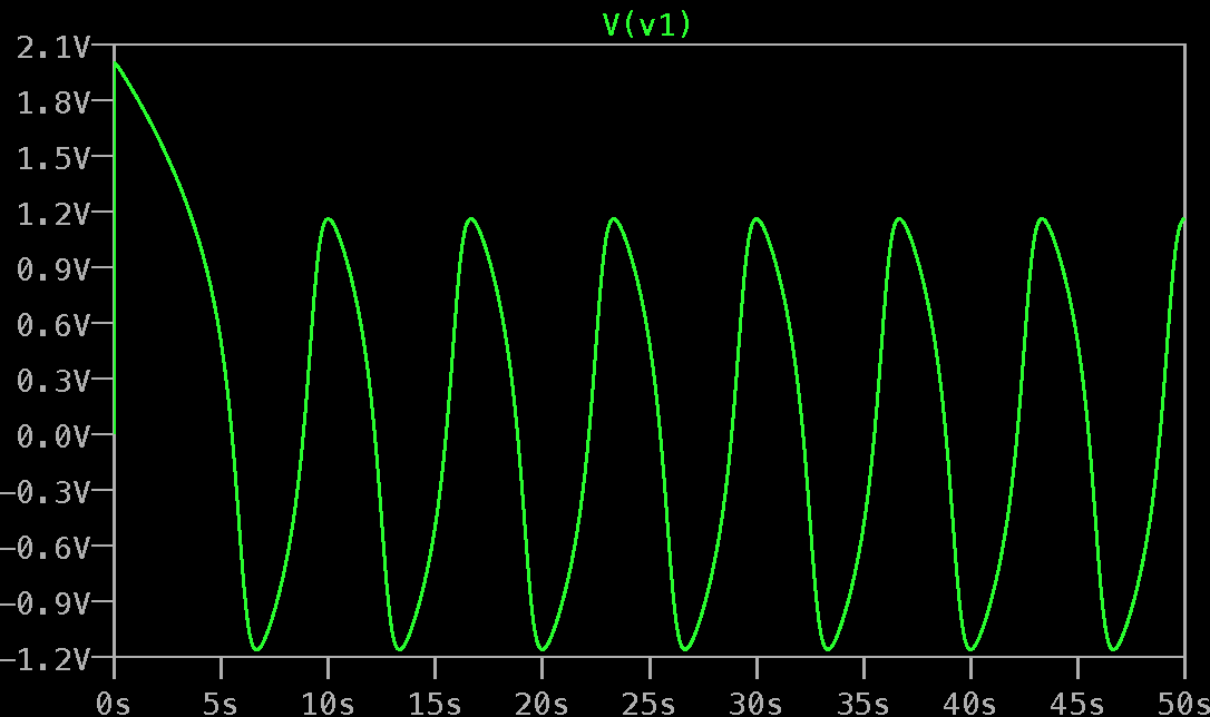
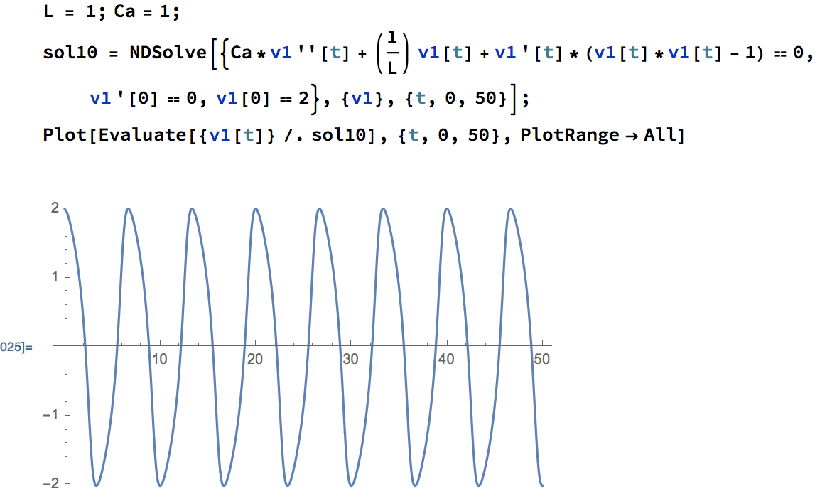
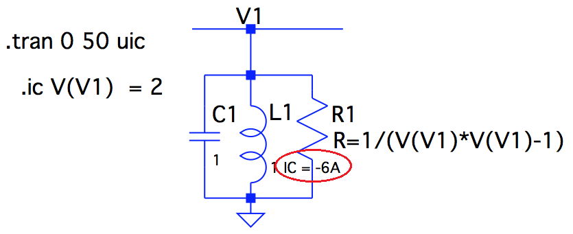
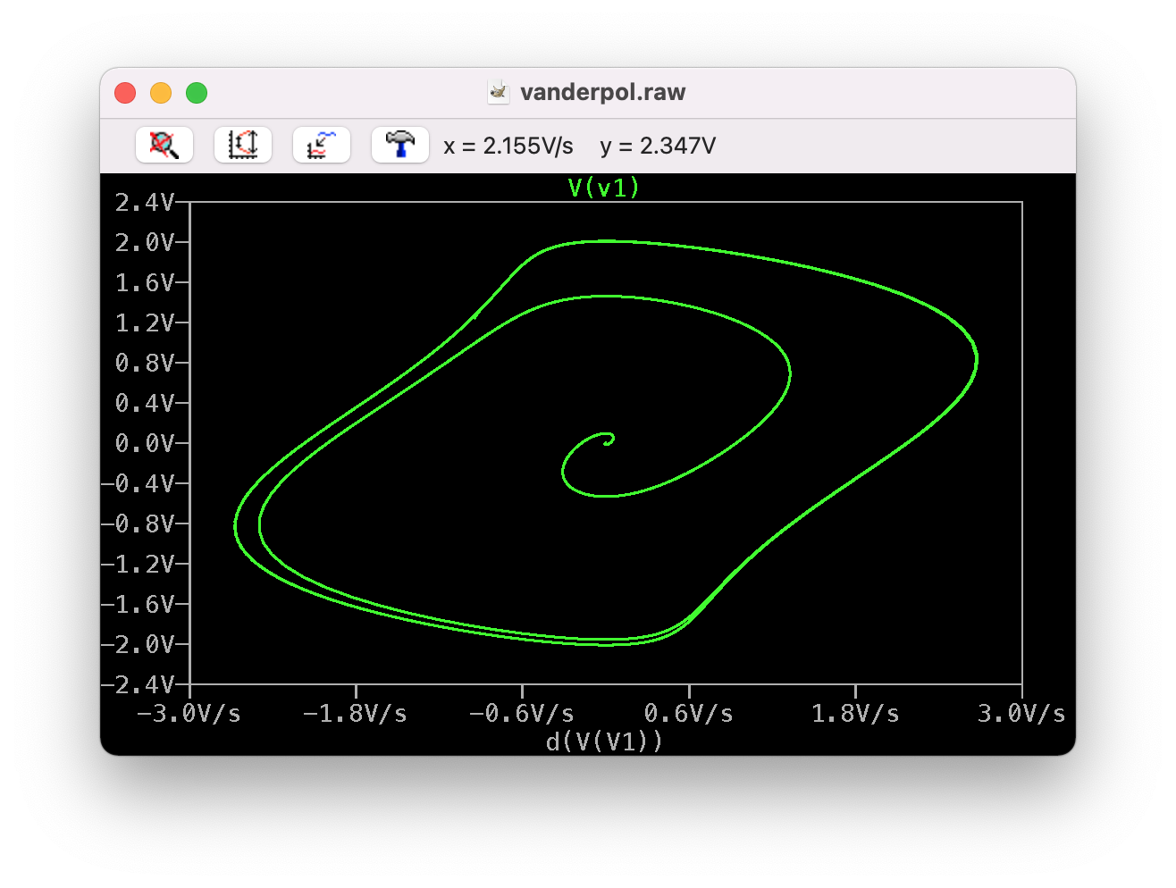
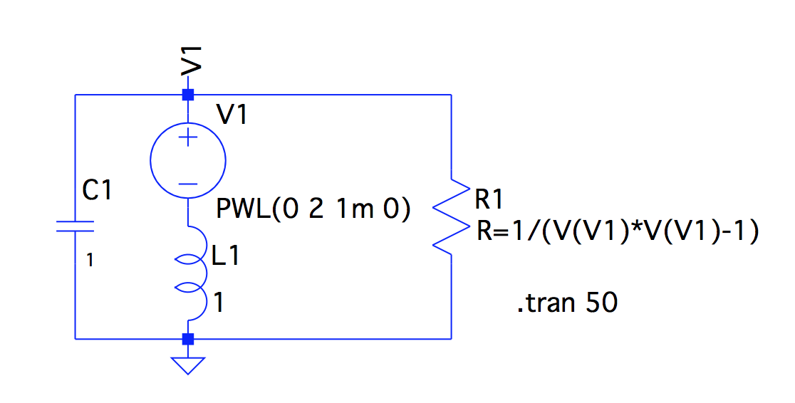
I am trying to simulate the oscillator with an RLC circuit with the initial condition V(V1) = 0 and D(V(V1)) = 0. Since LTspice does not allow initial condition with time derivatives, I set the initial current of the inductor to be -6A. (Initial resistance is 1/3 ohm, and initial current through the capacitor is zero.) The node V(V1) does show a limit cycle behavior, but the amplitude(around 1.2V) is different from the numerical result in Mathematica(2V). I have set all serial and parallel resistance/inductance/capacitance to be zero for the components. Any suggestions on what could be wrong? Thanks in advance for any advice!

schematic

LTspice result (limit cycle)

Mathematica result

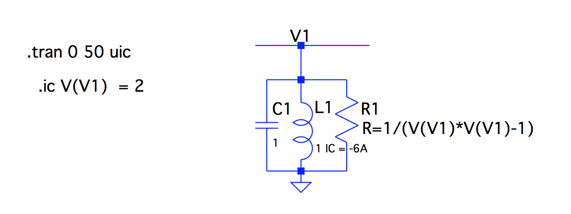
Edit: I have also tried using a physical circuitry to initiate my circuit. Yet the voltage of limit cycle is still 1.2V.New schematic
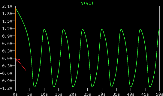
Also, if I change the resistance in my Mathematica file to be 1/(3*V(V1)*V(V1)-1) instead of 1/(1*V(V1)*V(V1)-1), the voltage response is exactly the same as the result in LTspice. (The first plot in the picture below is when I change the expression of the resistance, and the second plot shows the overlap with LTspice result.)
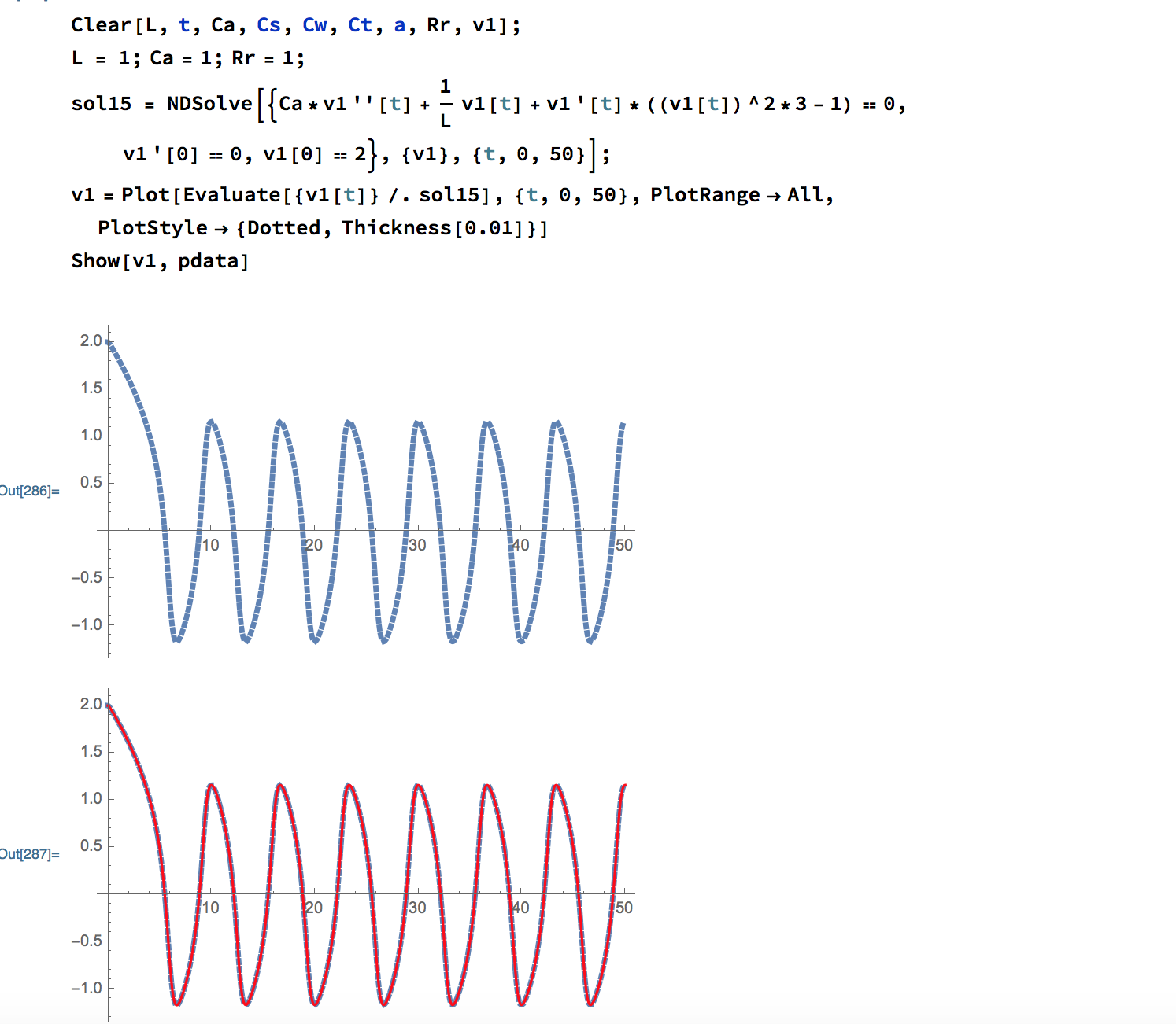
Overlap when changing coefficient On the other hand, all voltage responses scale proportionally as expected. For instance, when the resistance in Mathematica is 1/(V(V1)*V(V1)-4), the amplitude doubles and becomes 4V. The amplitude in LTspice also doubles to be around 2.4V when resistance is 1/(V(V1)*V(V1)-4).

\$\endgroup\$

3 Answers 3

1
\$\begingroup\$

Regarding the implementation in LTspice

Don't use the options "start up" or "uic" when simulating such circuits. Only use the initial conditions.
Using "uic" makes V(v1) still start at 0V.

enter image description here

Next, your circuit shows the initial condition .ic V(V1)=2 but the condition for i(L1) seems not implemented correctly:

enter image description here

I tested/confirmed by simulation that you made the inductance of L1 equal to 1 IC=-6A.
So, change the inductance value back to 1. And add the initial condition for L1 to the one for V1 like .ic V(V1)=2 i(L1)=-6A

However, this will still not give the same result as Mathematica(2V).

Regarding the implementation of Van der Pol oscillator
I wasn't sure if OP's circuit was a good implementation of a Van der Pol oscillator, but a quick KCL shows it does:

$$i_C + i_R + i_L = 0$$ $$ C v1' + \frac{1}{R}v1 + \frac{1}{L} \int v1 = 0$$ $$ C v1'' + \frac{1}{R}v1' + \frac{1}{L} v1 = 0$$ Substituting $$ C=1 \text{, } L=1 \text{ and } R = -\frac{1}{\mu(1-v1^2)} = \frac{1}{\mu(v1^2-1)} $$ yields the Van der Pol equation:

EDIT Regarding the implementation of Van der Pol oscillator
Noting the other answer I found the deduction above is incorrect.
R is dependent to v1, so substition afterwards is incorrect.

$$i_C + i_R + i_L = 0$$ $$ C v1' + \frac{1}{R}v1 + \frac{1}{L} \int v1 = 0$$

At this point the substition should be done because, next step, the derivative to v1 is taken, while R depends on v1. For that reason R should be defined as follows:

$$ R = -\frac{1}{\mu(1 - \frac{1}{3} v1^2)} $$

$$ C v1' - \mu(1 - \frac{1}{3} v1^2) v1 + \frac{1}{L} \int v1 = 0$$ $$ C v1' - \mu v1 + \mu \frac{1}{3} v1^3 + \frac{1}{L} \int v1 = 0$$ Taking the derivative to v1: $$ C v1'' - \mu \text{ } v1' + \mu \text{ } v1^2 \text{ } v1' + \frac{1}{L} v1 = 0$$ $$ C v1'' - \mu (1 - v1^2)v1' + \frac{1}{L} v1 = 0$$

Substituting $$ C=1 \text{, } L=1 \text{ and } \mu=1$$ yields the Van der Pol equation: $$ v1'' - \mu(1-v1^2)v1' + v1 = 0$$

Doing the simulation with .ic V(V1)=2 I(L1)={-(2*2/3-1)} will give the correct response.

\$\endgroup\$
2
  • \$\begingroup\$ Thanks a lot for the suggestion! I have also tried initiating it with a voltage source (schematic is attached above), so the initial condition is exactly V(V1) =2 V and I(L1)= -6A, but there is no improvement. \$\endgroup\$
    – LSY
    Commented Jul 11, 2019 at 0:45
  • \$\begingroup\$ I think you are right! Thank you so much for your help! \$\endgroup\$
    – LSY
    Commented Jul 14, 2019 at 1:06
0
\$\begingroup\$

LTspice might have been using the definition R = dV/dI to calculate the response instead of R = V/I.

When R = 1/(V^2-1), I = V/R = V^3-V. Hence if R = dV/dI is actually being used, R = (dV/dt)/(dI/dt) = 1/(3V^2-1) instead, which fits the plot in Mathematica.

I tried a few other values of resistance, such as R = 1/(V^4-V^2) in LTspice, and that corresponds to R = 1/(5V^4-3V^2) in Mathematica.

\$\endgroup\$
1
  • \$\begingroup\$ I've done a simulation implementing the R with an Arbitrary Behavioral Current Source (B sources) and it gave the same output. So, if the definition of R should be doubted, that still wouldn't solve the same mismatch between Mathematica and the circuit with a B current source. \$\endgroup\$
    – Huisman
    Commented Jul 13, 2019 at 18:46
0
\$\begingroup\$

Interestingly, this will also work (with the corrected expression for R) with .ic V(V1)=2 I(L1)=0 but not with just .ic V(V1)=2. You can, of course, use very small initial values for V(V1) and see the oscillations grow over time to reach the the limit cycle. Using .ic V(V1)=1u I(L1)=0 it takes approx. 35 secs to reach the limit. You can also plot the state-space diagram by plotting d(V(V1)) on the horizontal axis... enter image description here

\$\endgroup\$

Your Answer

By clicking “Post Your Answer”, you agree to our terms of service and acknowledge you have read our privacy policy.

Not the answer you're looking for? Browse other questions tagged or ask your own question.