4
\$\begingroup\$

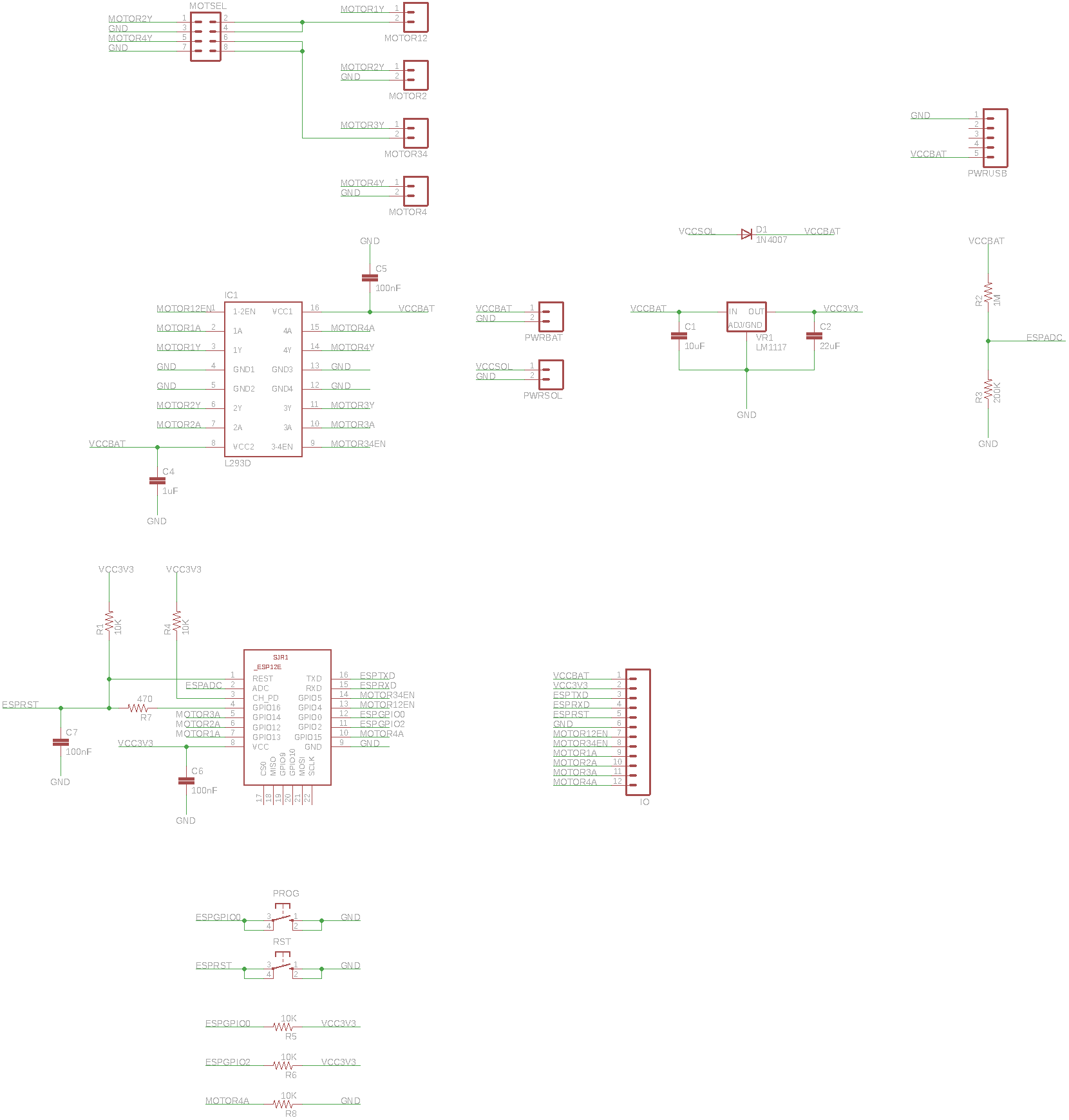
I have built an IOT motor controller board that's powered by 4 AA NiMH batteries in series. I want to use a solar panel to trickle charge the batteries, but the voltage slowly decreases even when the ESP12F WiFi module is sleeping and there's full sunlight on a 5v 200mA or 6v 150mA panel.

Why am I never seeing an increase in voltage?

enter image description here

\$\endgroup\$
6
  • 1
    \$\begingroup\$ Welcome to EE.SE! Unanswerable without more information. What sleep state current consumption does your board consume? What current do you measure from the solar panel? \$\endgroup\$
    – winny
    Commented Jul 10, 2019 at 11:38
  • \$\begingroup\$ @winny I measured 90mA in normal mode, 40mA in sleep mode, and only 35mA from the 6v solar panel. Would I then need two of these solar panels in parallel in order to see the battery voltage increase? \$\endgroup\$
    – inc
    Commented Jul 10, 2019 at 15:28
  • \$\begingroup\$ 40>35 so you are depleting your batteries at at rate of 5 mA when the sun is shining and 40 mA when it’s not. You need more solar power or less consumption. Hint: sleep mode usually means uA. \$\endgroup\$
    – winny
    Commented Jul 10, 2019 at 16:33
  • \$\begingroup\$ After measuring the current I realized that the L293D becomes enabled when the ESP is sleeping. I added pull-down resistors to the motor enable pins and the sleeping current has now reduced from 40mA to 19mA. \$\endgroup\$
    – inc
    Commented Jul 11, 2019 at 9:09
  • \$\begingroup\$ Better, but aim for <1 mA for any sleep application. \$\endgroup\$
    – winny
    Commented Jul 11, 2019 at 10:34

3 Answers 3

4
\$\begingroup\$

You are not seeing an increase in your battery voltage for two reasons:

  1. The solar cell is NOT providing its full current/voltage capability, so your perception of 'full sunlight' is wrong. Test your solar panel on it's own and use a light meter to get some idea of the span of capability the panel has.
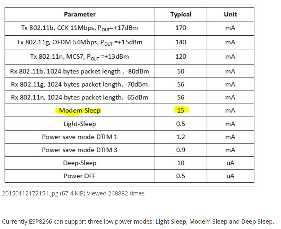
  2. Your ESP12F IS NOT asleep, it's just in a lower power mode.

See here:
enter image description here

You should be aiming to be in at least Modem-Sleep mode, and even at this, you will have limited runtime for dark periods if your IOT device is expected to be always on/ready.

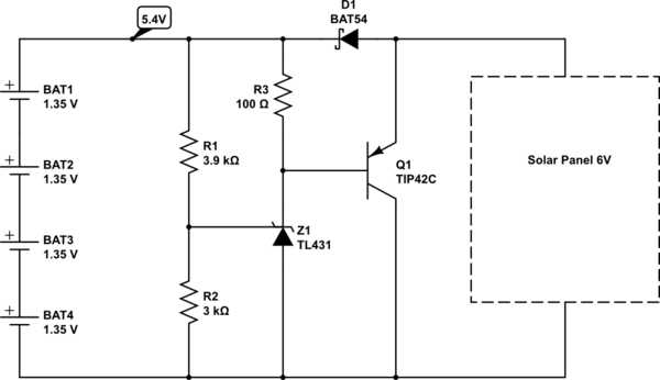
For your solar battery charge schema you absolutely must have at least a voltage threshold sensor. As commented in another answer this could be as simple as a TL431 and transistor. Since you might have to dissipate all the power from the solar panel the TL431 on its own won't do.
This type of wasteful charger is ok, but means you can never fully charge the batteries since you have to make voltage compromises. However it's cheap so may be all you need.

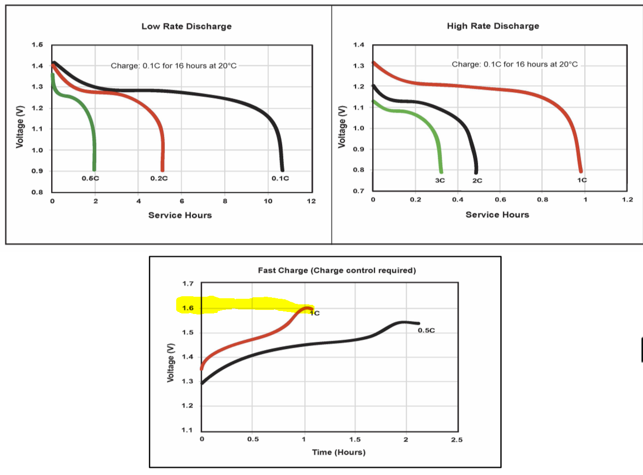
For example if you used this Duracell AA NiMH you can see the problems with a voltage only controlled charger:
enter image description here

To charge the batteries (nominal 1.4V, so 5.6V pack) at maximum rate you need a peak voltage of about 6.4V ...above you panel capability. This assumes active charge current control and would add complexity and cost to your project.

To charge the batteries with a voltage only control, you have to set the voltage to no more than the expected terminal voltage (and this varies with temperature too). In this case a reasonable choice would be 1.35V (5.4V pack). At 5.4V pack voltage you will get a proximately 80% charge on the batteries.

At this voltage the batteries will never overcharge, and even though the charge current reduces to just a few mA for a long time this IS NOT trickle charging. Trickle charging by definition is continuing to charge the battery AFTER it is fully charged. In this case since we are not fully charging the battery there is no problem with low current charging.

With a simple charger like this you have to dissipate most of the energy from the solar cell when the voltage limit is reached. In this case if the panel current limit is 200mA then you need to dissipate about 1.2W.

I'd suggest a circuit such as this:
schematic

simulate this circuit – Schematic created using CircuitLab

\$\endgroup\$
6
  • \$\begingroup\$ What would happen without the voltage threshold sensor? \$\endgroup\$
    – inc
    Commented Jul 11, 2019 at 9:19
  • \$\begingroup\$ Battery charger ICs are pretty much a commodity these days, thought. You could say that the main problem is picking a suitable one from hundreds of choices, they come in various sizes, shapes and capabilities. It's going to set you back by £2-4 for single pieces or so. For a hobbyist the main problem is that the nice ones usually have a thermal pad which requires a proper PCB and would really benefit from reflow processing as well. 6V panel is inconveniently close to the battery voltage for a simple low side current limiter type charger. \$\endgroup\$
    – Barleyman
    Commented Jul 11, 2019 at 13:09
  • \$\begingroup\$ Maybe designing full-fledged charger circuit is a bridge too far. I'd suggest looking at off-the-shelf charger for solar cells and putting two panels in series to ensure panel volta >> battery voltage when there's light available. \$\endgroup\$
    – Barleyman
    Commented Jul 11, 2019 at 13:16
  • \$\begingroup\$ @inc Without the voltage sensor you will overcharge the batteries. Not a great idea. \$\endgroup\$ Commented Jul 11, 2019 at 14:06
  • \$\begingroup\$ In the meantime maybe it would be possible to stop sleeping when the battery voltage gets too high, in order to prevent overcharging? Any suggestions for an IC that can handle all of the charging circuitry? I would like everything integrated onto the PCB. More important than cost is simplicity of implementation, so I'm less likely to screw up the next board revision. \$\endgroup\$
    – inc
    Commented Jul 12, 2019 at 8:10
4
\$\begingroup\$

You should be able to measure the sleep mode current draw and determine where the current is going.
Always active are the L293, the LM1117 and the sleeping ESP.
None of these should be close to the notional 150 mA PV input current.
The most likely "rogue" load is the ESP not being in sleep mode.

You MUST NEVER "float" modern NimH batteries. Older batteries under about 1800 mAh had the capability to absorb up to about C/10 trickle charging (about <= 180 mA). Modern cells above that capacity do not have that capability and there is no certainty that lower capacity modern ones still have trickle charge capacity. Charging fully charged NimH cells will destroy them rapidly by electrolysing the electrolyte and drying out the cell.

To "float" NimH cells long term you can absorb ALL trickle charge current by voltage clamping them at 1.45V per cell at 20 C = 5.8V for 4 cells (or lower). Your nominal 6V PV input + D1 notionally limits the voltage to under 5.8V BUT in practice it may not. Use of a zerner is suitable ONLY if it is certain to keep the voltage to <= 5.8V. Otherwise a hard clamp using a sharp cutoff clamp regulator such as a TL431 and appropriate pass transistor is recommended.

\$\endgroup\$
1
  • \$\begingroup\$ 1.45V would certainly work at 20degC, BUT is likely above fully charged at freezing point. If the charger is simple and temperatures extend from 0-40 degC (IMO this is the minimum you should design for) then you need to set the voltage cutoff less than 1.45V or you will certainly shorten the battery life. \$\endgroup\$ Commented Jul 12, 2019 at 14:27
1
\$\begingroup\$

You need overvoltage to charge NiMH batteries, or batteries in general for that matter. Do note where it says that constant voltage charging is not a good idea, you need to control the current.

According to Wikipedia, the minimum charging voltage is 1.4V per cell so you'd need 4x1.4 = 5.6V to charge it. You should check the charging voltage to make sure it actually is high enough and design some kind of current limiting circuit.

https://en.wikipedia.org/wiki/Nickel%E2%80%93metal_hydride_battery#Charge

\$\endgroup\$
6
  • \$\begingroup\$ FYI: 1.4 or 1.45V/cell is an OK constant charge voltage at C/10 rate or lower. At higher rates a somewhat higher voltage can be used. Voltage MUST be clamped at a suitable level or cells will trickle charge indefinitely and will be destroyed quite rapidly. [[I have a million NimH cells in solar torches and that "knowledge" is derived from substantial practical experience. ]] \$\endgroup\$
    – Russell McMahon
    Commented Jul 10, 2019 at 11:45
  • \$\begingroup\$ @RussellMcMahon The key bit here is "at C/10 rate", if you have no knowledge of the charge current, you won't know what's going on if you control output voltage only. The cells may be subtly different and/or some cells have charge, some do not and so on. If we presume nothing catastrophic will happen at 1.4V (or 1.45V) / cell, you can just use CMC SMPS set to an appropriate output voltage, it will go into pulse skipping mode when Iout drops low enough and/or Vout exceeds set point but beware of a syncbuck capable of draining current. You'd probably want hysteretic control too. \$\endgroup\$
    – Barleyman
    Commented Jul 10, 2019 at 14:22
  • \$\begingroup\$ You cannot simply pick a voltage and hard regulate that. If the cells are fully depleted this may well over current them. Connected to a solar cell you have a 'soft' voltage ...draw more current and the voltage will drop. Under these conditions you can get away with selecting an endpoint voltage, but I'd suggest 1.4V is too much. If you assume that 120DegF is not an unusually high temperature, then the terminal voltage at full charge will drop below 1.4V. \$\endgroup\$ Commented Jul 10, 2019 at 18:17
  • \$\begingroup\$ @Barleyman Indeed. <= C/10 IS a key factor here (which is why I said it). He has sources rated at 150 or 200 mA. Almost all modern AA NimH are >= 2000 mAh so qualify for C/10 here. When I established that figure I obtained every brand of rechargeable AA NimH I could and did a large number of tests in a temperature controlled environment from 20 C up to "far too hot". || This aspect which I addressed is of course not what the question was mainly about (which was undercharging). I just thought it a really good idea to address. If the OP shows interest more time can be spent on it. \$\endgroup\$
    – Russell McMahon
    Commented Jul 11, 2019 at 2:45
  • \$\begingroup\$ @JackCreasey I agree in the fully general case. In this case the OP specifies Icharge of 150 or 200 mA. I noted Ichg <= C/10 which implies a capacity of >= 2000 mAh. Most modern AA NimH are above that. See my response to Barleyman. I established that voltage after tests on every brand & model of AA cell I could find and in temperatures ranging from under 20 C to somewhere in the 50C range (maybe higher (this was in 2008 I think)). The 1.45V figure was a safe one at which no cell ever "ran away". 1.4V is safer again. Too high and they charge forever and self destroy. \$\endgroup\$
    – Russell McMahon
    Commented Jul 11, 2019 at 2:50

Your Answer

By clicking “Post Your Answer”, you agree to our terms of service and acknowledge you have read our privacy policy.

Not the answer you're looking for? Browse other questions tagged or ask your own question.