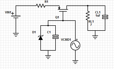
You've got two things happening when you pull VCMD low to get the FET to conduct: you're discharging C1 and discharging the gate capacitance of the FET. I would also recommend using a resistor directly on the FET gate to control your current flow to/from VCMD. The datasheet gives the values for a general use case with the time delay on/off and the rise/fall times at the bottom of the "Electrical Characteristics" table.
It looks like it takes 50ns to conduct given a -10V drive signal through a 6.8 Ohm gate resistor with a 12 Ohm load to a -75V supply. Alternatively with the same setup and a 0V drive signal it takes 90ns to turn off. This isn't exactly your use case but it may be close enough if you mimic the gate resistance and drive voltages (Figure 10 in your datasheet shows the schematic of the test setup).
For a more tailored answer to your application, MOSFET gates act like capacitors that you have to fill/empty to get past the threshold voltage to switch from conduction to non-conduction or visa versa. MOSFET drivers exist in high power applications to really slam the capacitors around to get the fastest on/off switching times possible by providing high currents to quickly source/sink charge. This limits the time the MOSFET spends in the linear conduction region where there's a voltage drop between the source and drain, therefore burning power (conduction losses). On the other hand, resistors are used on the gates to prevent infinite currents gate charge/discharge cycles from burning out control circuitry - this increases conduction losses because it slows switching speeds. So for driving FETs, that's an engineering tradeoff because higher current drivers adds cost, complexity and electrical noise.
Check this application note from Vishay for more detailed calculations to get switching time from the datasheet values for your particular use case:
https://www.vishay.com/docs/73217/an608a.pdf
FYI just because you don't have a gate capacitor doesn't mean that it will respond infinitely fast, your microcontroller GPIO pin or other gate driver will have a Thevenin equivalent that will tell you what your effective "gate resistance" is at the Thevenin equivalent voltage, this is a way of looking at your gate driver's source impedance (which is critical to know how fast you can switch the FET).

