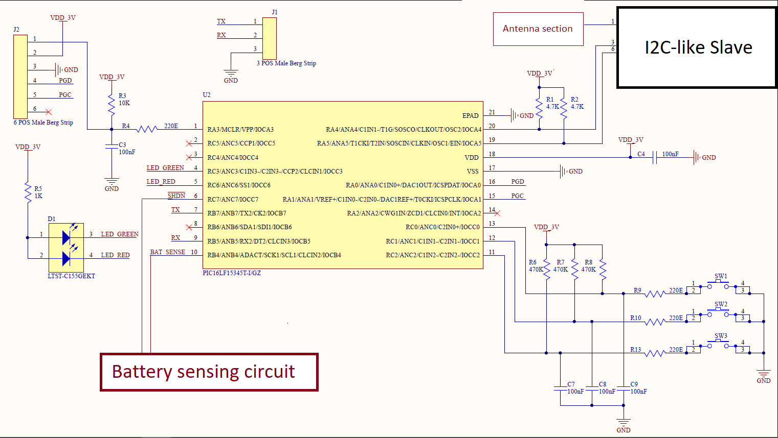
This might appear as one of those tens of questions that ask about power consumption on a PIC microcontroller. But after I have failed to reduce the current consumption to an acceptable level despite of the fact that I tried most of the suggested guidelines in those question here, I have decided to ask a separate question anyway.
- Microcontroller: PIC16LF15345
- May not relevant but Development environment is MPLAB X v5.20, XC-8 Compiler v2.00. (Free versions)
- Operating at: 3.0 V and at 25 Degree Celsius. There is no regulator on board. It shall operate on a CR2032 battery.
- Unused pins are NC on board, no pull-down/up provided.
The design requires the following:
- System operates on internal HF oscillator, 1 MHz.
- 3 GPIOs (Digital Inputs, Switches, pulled up through an external 470k resistor). System spends the most time in SLEEP mode with occasional wake-up through these switches.
- Analog voltage measurement through internal ADC, interval FVR (Fixed Voltage Reference of 1.024V).
- Interface a I2C-like protocol by bit-banging implementation. Data and Clock lines are pulled high via 4.7k resistor.
- Two LEDs (Digital outputs), made Low to turn ON, made high to turn OFF.
- A Timer is required for some application-specific behavior when system is active.
- A UART for configuration. Desired: System should wake-up when a command is sent from UART, process it and then sleep again. Shall take place very rarely, possibly once in an year.
Schematic:
Note: For this troubleshooting, we have removed the I2C-like slave chip from the board, so it is not consuming any current. Along with that the following have been removed for testing: Both LEDs, R1, R2, R6, R7, R8, R9, R10, R11, C7, C8, C9. I understand that with these removed, there is no way to wake-up the system from sleep mode. For now, Watchdog and BOR are disabled.
My understanding:
Before going into sleep mode (by SLEEP instruction), the code should implement the following:
- Since LEDs are removed, the pin is made Low.
- Unused pins should be configured as Output and made Low. PGC and PGD pins should be considered unused and hence be configured just the same way.
- Timer module halted, disabled. Timer interrupts disabled.
- ADC module disabled, FVR disabled. ADC interrupts disabled.
- Disable Global interrupts.
- Clear the IDLEN bit in CPUDOZE register.
I have connected a multimeter in series with the supply. I know its not the correct way of measuring the current, and I have asked someone to connect a resistor in series with supply and measure the drop across it. I implemented the code with above understanding/considerations, the current consumption when system is in sleep mode is 10 uA. The datasheet claims the sleep mode current to be 50 nA @ 1.8V (Page 1).
What have I already looked into:
- Datasheet
- PIC tips and tricks for Low Power by Microchip
- Deep sleep mode consumption of PIC
- Reducing current consumption in deep sleep mode
Questions:
- Is the process that takes place before SLEEP mode is entered correct?
- What else can we do in Hardware and/or Firmware to reduce the current consumption?

