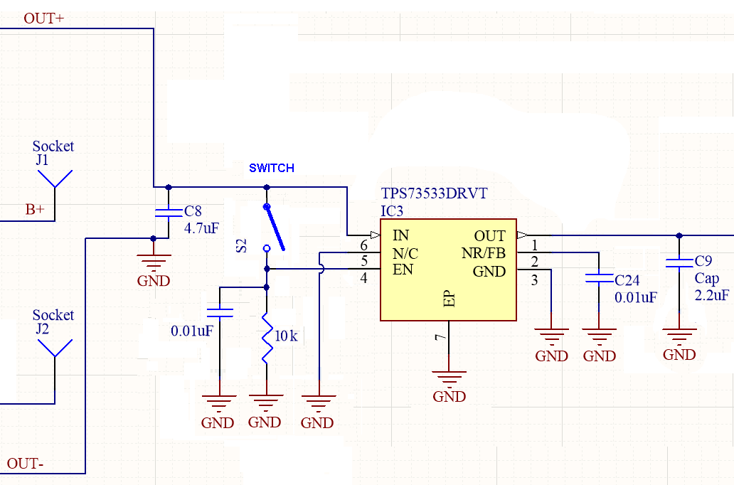
I had something like this come up in a job interview once. I thrashed around for a hardware-only answer (and I’m not so shabby in this area.) However, the solution they wanted to hear was have the MCU control the main power switch, and the button would ‘force’ the power on until the MCU would hold it on. They expected the user to hold the button until they got visual feedback that the device was ‘on’.
That was their shibboleth.
You see, I had become so used to (or should I say, worn down by) lazy, unimaginative and change-averse software people who would have been unwilling to deal with such a low level problem (or I would have had to push for it three levels up the food chain), that it didn’t occur to me that the host could do this.
I don’t work at that place anymore thankfully. And I didn’t get the job, either - but was able to go on a monthlong trek instead as I had enough vacation saved up. So, things worked out.
tl; dr version: button to power on, MCU GPIO to hold it on.
EDIT: A basic circuit uses 2 diodes, a FET and two GPIOs.
- Diode D1 to switch and VREG enable (anode toward switch)
- Diode D2 to MCU GPIO#1 and VREG enable (anode toward MCU)
- N-FET Q1 switch to gate, drain to MCU GPIO#2, GND to source
- pullup on FET drain to MCU power
- pulldown on VREG enable
- pulldown on SW
The way this works is as follows:
- Power off, SW is open (initial power on): VREG enable pulled down
- Power off, SW is closed: VREG enable pulled up to start up.
- Powering up: MCU starts, takes GPIO#1 high, pulling VREG enable
high through D2.
- Powered on, SW is open: GPIO#1 keeps enable on through D1
- Power on, SW is closed: Q1 turned on. Pulls GPIO #2 low. MCU begins shutdown, then takes GPIO #1 low to turn the power off.
- Powering off: Power turns off when user releases SW1.
This is a very cheap way to do this. A compact way would use a Silego, powered by VBUS.


