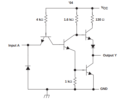
I'm learning about electronics and was studying the SN7404 hex inverter schematic when I saw this:
I naively expected just a single transistor (the one in the bottom right) and the input at the base of that transistor to give the inverted input at Output Y.
Yet there are 3 other transistors, a bunch of resistors and a couple of diodes in addition.
Can someone here help to explain what the purposes of these are and the reason for the resistor values?
Source datasheet here: http://www.ti.com/lit/ds/symlink/sn54ls04-sp.pdf

