0
\$\begingroup\$

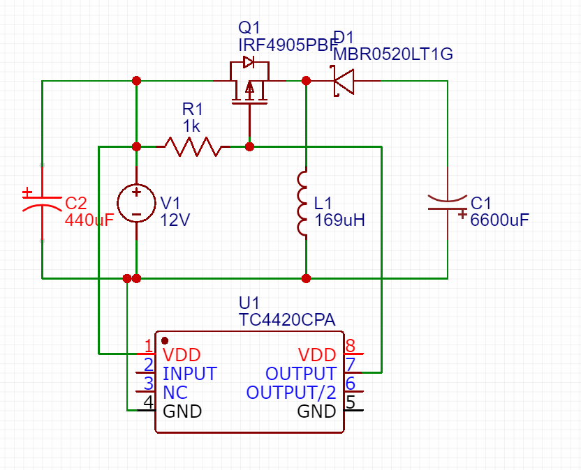
I have currently wired up this inverting buck-boost converter circuit:

enter image description here

However, when driving the input of the TC4420 with a 62.5kHz square wave with a 40% duty cycle, the power supply overcurrent triggers and shuts off. After a few attempts, the MOSFET fails with the gate shorted to source and drain.

2 MOSFETS have already died this way. What is wrong with my circuit?

\$\endgroup\$
3
  • \$\begingroup\$ Note that as shown, you have a conducting body diode in series with the inductor, so the circuit is guaranteed to blow the FET if the input supply has enough current to do so. \$\endgroup\$
    – John D
    Commented Jul 21, 2019 at 17:04
  • \$\begingroup\$ The schematic doesn't look like it describes your circuit (see Huisman's reply). Please post the links to datasheets for C2 and L1. \$\endgroup\$
    – bobflux
    Commented Jul 21, 2019 at 17:21
  • \$\begingroup\$ It seems I've made a few errors in drawing this schematic. I will update it later, but the mosfet is indeed connected with the source and drain swapped. \$\endgroup\$
    – Evan Chen
    Commented Jul 21, 2019 at 17:25

2 Answers 2

3
\$\begingroup\$
  • The body diode of the p-channel mosfet is forward biased, so it will always conduct through L1 which makes it fry: swap the drain and source of the PMOS.
    Figure 12 of https://www.allaboutcircuits.com/technical-articles/analysis-of-four-dc-dc-converters-in-equilibrium/ and some other pictures on the internet incorrect as well.
  • The mosfet driver is missing its input signal.
  • Pin 8 and 5 are floating, but should both be connected.

    The ground pins are the return path for the bias current and the high peak currents that discharge the load capacitor. The ground pins should be tied into a ground plane or have very short traces to the bias supply source return.

    The VDD input should be bypassed to ground with a local ceramic capacitor. The value of the capacitor should be chosen based on the capacitive load that is being driven. A minimum value of 1.0 μF is suggested.

\$\endgroup\$
0
\$\begingroup\$

Turns out, the problem was unrelated to the design of the circuit but rather the startup of the input signal. The input signal defaulted to ground, which resulted in the mosfet shorting the power supply across the inductor. Connecting the ground wire of the Arduino last when powering up the circuit has fixed this issue.

\$\endgroup\$
2
  • 1
    \$\begingroup\$ I take it that the other problems Huisman pointed out are problems with your circuit diagram, and not problems with your actual circuit? \$\endgroup\$ Commented Jul 22, 2019 at 1:07
  • \$\begingroup\$ That's correct, unfortunately my diagram was very hastily drawn. The mosfet is oriented correctly, the duplicate pins are tied together, and the input signal is connected. \$\endgroup\$
    – Evan Chen
    Commented Jul 22, 2019 at 4:36

Your Answer

By clicking “Post Your Answer”, you agree to our terms of service and acknowledge you have read our privacy policy.

Not the answer you're looking for? Browse other questions tagged or ask your own question.