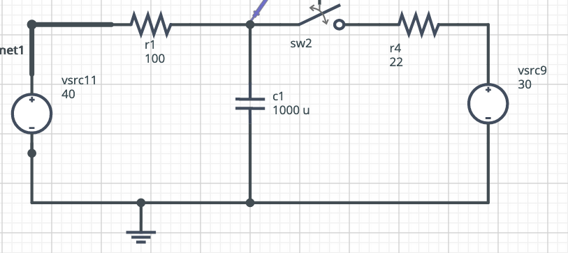
I have this circuit:
This circuit is working for a long time like this, with the switch open. So, the circuit is stabilized and the voltage across the capacitor is 40V.
At t=0, the switch is closed.
What is the voltage across the capacitor 3ms after the switch is closed.
MY SOLUTION
After the switch is closed, the capacitor will change its voltage to match the one imposed by the voltage divider composed of R1 and R4.
At the left side of R1 there is 40V and at the right side of R4 there is 30V.
If we remove the capacitor, we can calculate the current in the circuit to be
\$V = RI\$
\$(40-30) = (100 + 22)I\$
\$I = 81.96mA\$
So, the voltage drop across R1 is equal to
\$V_{R1} = 100 x 81.96mA = 8.1967V\$
So the voltage between the resistors is
\$V_{div} = 40 - 8.1967 = 31.80V\$
This will be the voltage across the capacitor after stabilization.
So far, so good. This matches the value I get from the simulator I am using.
Now I want to know the voltage across the capacitor 3ms after it starts discharging.
If I substitute both voltage sources with wires, I see that the capacitor is in parallel with R1 and R4, what gives me an equivalent resistance of 18.0327.
Now I use
\$V_c(t) = V_s e^{-\frac{t}{RC}}\$
\$V_c(3ms) = 40 e^{-\frac{3e-3}{18.0327 x (1000 e-6)}}\$
\$V_c(3ms) = 33.8695V\$
The problem is that when I simulate that using software simulators I get the voltage across the capacitor after 3ms to be 38.7438V.
What is wrong?

